One of the more functional mods I’d been planning for some time was the addition of a Raspberry Pi with OctoPrint for wireless control and remote monitoring of prints (by webcam).
OctoPrint is essentially a host software for 3d printers that allows you to control the printer remotely via a web interface. It has the same basic functionality as Repetier-Host, Pronterface (PrintRun), Cura or MatterControl but is really designed for printing untethered, most commonly by installing OcotoPrint onto a Raspberry Pi (I imagine there are other ways to do it).
If you’re not already a 3d printing enthusiast, this may seem incredibly confusing already. The success of the RepRap movement has created a situation where most of the best software out there for 3d printing is open source and hardware agnostic, meaning that folks are free to pick and choose the modeling software, slicing software, host/control software and even the firmware that actually resides on the 3d printer’s control board and then mix and match to suit their needs or interests. Yes, it can make troubleshooting challenging.
OctoPi is essentially a distribution of OctoPrint that has a lot of the common features and extras built in, just to make it easier for newbies like me to get up and running as far as I can tell. Kudos for that.
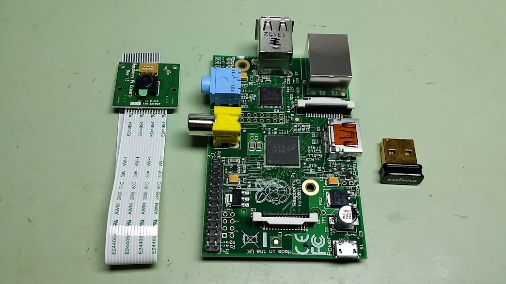
I picked up the Pi and the extra goodies back in May I guess (sheesh) but was so into the compensating bed mounts modification that I didn’t take the time to start working on it until recently. I followed Mochaboy’s long, detailed and mostly complete thread on printrbottalk forums to get OctoPi installed on the Pi, get the Pi talking to my router and get the camera working and everything pretty much went as expected. Then came the challenge of trying to stick the thing in the bot.
In case you haven’t been following along, the Printrbot GO! (v.1) is a 3d printer in a suitcase and, as such, is not long on extra space. I’ve further cramped the situation by adding an LCD panel and encoder; tools under the bed and little bottles of Aquanet, Windex (and later gluestick) inside a side panel; a scraper for cleaning the bed and a thermometer and hygrometer. But it turns out that after much head scratching, I was able to find a home for the Pi (inside a simple, low-profile case I printed out for it) inside the right hand panel on the front of the bot.

This location also allowed me to attach the Raspberry Pi camera onto the side of the gantry and have just enough room for the ribbon cable to reach from Z=0 to Z=155. I designed and printed a clip on mount with an articulated elbow and slim case for the camera and was in business.

You may be able to ascertain by the way I casually mention this that it took me several if not dozens of attempts to get a properly printed Raspberry Pi camera case that I was happy with. But anyway, the journey is the destination, right? And anyway, the end result is satisfactory.

The brilliant thing about having the Raspberry Pi camera working in conjunction with OctoPrint is that it allows you to remotely monitor the printing progress. Previously I would have to get up from the couch in the living room and go back to my office/workshop to check on a print every half hour or so, but now I can just pull up the OctoPrint web interface on my phone and see how things are going.
It’s worth noting also that the Raspberry Pi camera can be refocused. The housing for the lens is glued in place, but with a little effort you can break the glue and unscrew it slightly to reduce the focal distance. Initially it had a focal distance in the 20 or 30 cm range approximately, but by unscrewing it just a little I was able to get it into the 15 cm range that is appropriate for where I have the camera mounted in my bot. And you can make time lapse videos too.
So now that I had the thing mounted, I had to figure out how to get it power and how to run the USB to micro-USB cable from the Raspberry Pi back to the Printrboard. The Raspberry Pi needs 5 volts and ideally in the vicinity of one full amp of current to make sure you don’t starve it when stuff is happening (or so I’ve been lead to understand anyway), so the 5 volt connections coming off of the Printrboard endstops (one of which – for the E endstop – is unused in my setup), at less than half an amp, would be insufficient. The X-Box 360 PSU I’m using to power my bot does have a 5 volt standby/power-on connection, but apparently it only puts out about 0.3 Amps, so also not a great option for feeding the Pi.
I had previously been running the entire 12 volts of the X-Box 360 PSU through the Frankenstein-style knife switch and found that the switch itself got pretty good and hot when running the bot with the heated bed. Too hot to touch comfortably in fact. Not a good thing. So I decided to wire that 5 volt standby/power-on connection from the X-Box 360 PSU through the knife switch instead, making the on/off action much closer to what the X-Box engineers had in mind to start with (I’m sure they envisioned their power supply running a steampunk inspired 3d printer in a suitcase, right?).
So in the process of rewiring that business, it started to make sense to just convert some of the plentiful 12 volt power to 5 volts as long as I could also keep the amperage in a safe range for the Pi. You know what’s a good way to convert 12 volt direct current to 5 volt direct current? A car charger. I just happened to have an old one lying around, so I gutted it, attached it inside the left hand panel above the LCD with zip ties and soldered in the leads from the PSU.

I decided to wire the positive 12 volt lead lead for the car charger through the auxiliary power switch (Brook/Ben intended it for switching between a power supply and a battery) so that I can turn the bot on without the Pi powered up if I choose.
Then to get the Micro-USB cable to fit inside the panel with the door closed, I had to stand the Printrboard off from the wood by a wee bit and decided to put a plexiglass guard in place to keep the ample bundles of wiring from interfering with the gantry while it’s in the Z=0 range. Both of the power and USB wires were secured to the various panels with little custom cable clips I designed and printed out for them.
You may also notice what looks like a piano wire or guitar string sticking off the bottom. That’s another guard that I installed to keep the wiring for the heated bed and compensating bed mounts from buckling up and interfering with the left side fan when moving around close to X=0.

The vestigial Z end stop is still there because of laziness and/or fear of needing it again some day. It’s not plugged in to anything.
I guess it’s worth mentioning a couple other mods I completed recently, one of which is visible above. I became disenchanted with my dual, articulated fan mounts due to the fact that they were always getting bumped and misaligned and I never really needed them to be pointing anywhere except for directly at the tip of the nozzle. Essentially the hard fought adjustability of the design had turned out to be a liability rather than an asset. I sketched up a fixed angle/position version in the shape of a donut with some amount of adjustability in the OpenSCAD file and, after a few iterations, arrived at something I was happy with.

The mount still has a rotating slide-lock design for easy installation and removal (like when changing hotends) and, although shown here in clear ABS, I ended up reprinting the mount and ducts in Taulman Bridge for maximum robustness. So far so good although I am toying with the idea of scaling up to 40 mm fans (these are 30s). I think I just have room. The design files are on YouMagine as “Dual Fan Mount Donut“.
I’ve also been playing with ColorFabb Bronzefill a little bit since it’s such an obvious choice for add-ons for a steampunk inspired 3d printer, but I’m not yet 100% satisfied with the results I’m getting yet. I’d like to be able to have an antique/oxidized patina on some parts and a nice polish on others, but it seems like I need to polish everything first in order to get the patina to properly darken the bronze particles. This is a little difficult on detailed parts without some kind of tumble/agitation polishing (I think that would work anyway), but I haven’t given up hope yet. I did make and install a new “speed dial” encoder knob out of Bronzefill that is pretty nice looking in my humble opinion. Perhaps you can see that the unpolished edges of the knob are too light colored, as are the interior edges of the fleur-de-lys. The top, flat surface has a nice polish that doesn’t show well in this picture. More to come undoubtedly.
