First, a disclaimer: I’m going to talk a lot about something that I will mostly call Z wobble in this post. I know there are folks in the RepRap community with strong ideas about what Z wobble really means as opposed to Z ribbing or various other artifacts and anomalies found on the vertical sides of printed walls, so please forgive me if I’m using the language incorrectly. What I will be talking about is the side to side shifting of layers caused (at least in part) by the threaded rods pushing the extruder off kilter by wee amounts as they push the gantry up layer by layer. It is not my intention to obfuscate or confuse, I’m just not interested enough to dig through the mountains of blog posts and forum discussions required to get to the bottom of whatever the current consensus may be on the proper terminology of this (these) issue(s). If you are a RepRap semantician and want to drop some knowledge on me – Come at me bro.
If you’ve been watching this space, you may know that I’ve gone through some threaded rods, some more threaded rods and still more threaded rods. I can’t say that every change has been a reaction to poor performance, but I was of course always hoping for better performance after-the-fact and generally did not find that to be the case. As it turns out, thinner rods will flex a little as needed to make up for any misalignment between the threaded rods and the linear rods, and this is a good thing. I had read this thing, but I did not know this thing to be true from experience. I now know this to be a good thing.
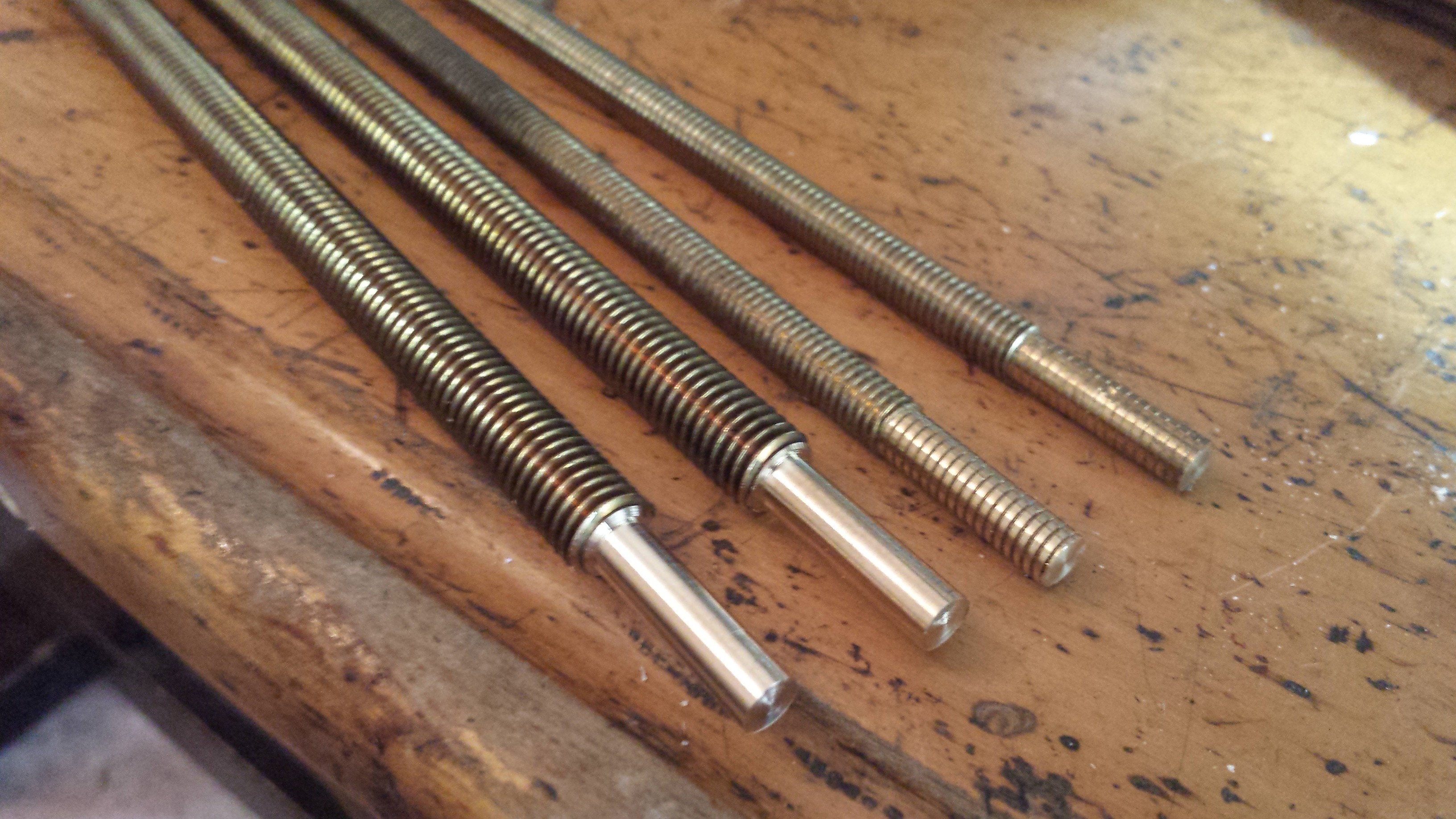
So when I switched from 6 mm threaded rods to 8 mm threaded rods, my Z wobble artifacts actually got worse. Then when I switched from 8 mm brass rods to 8 mm steel trapezoidal leadscrews, although I can’t say things specifically got worse, they didn’t get noticeably better. So then I started thinking about the couplers.
Most folks are in agreement that couplers with some flex in them are a good thing. Any misalignment between the threaded rods and the linear guide rods that might be present will be reduced if the threaded rods can lean slightly rather than pushing against the gantry. Since this misalignment is more likely an offset (the motor shafts and guide rods not being at precisely the same locations in the base of the bot as they are in the gantry) rather than a lean, an unfortunate artifact of having the motors at the bottom of the bot is that any side to side shifting caused by the offset will be more pronounced the closer you get to the bed. This is unfortunate because every print starts on the bed, so every print will suffer the greatest of these Z wobble artifacts (the ones caused by the offset – stay with me here).
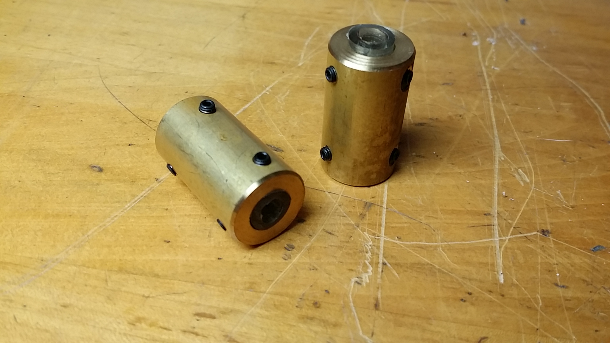
So I tried stiff custom couplers (out of brass), then the same couplers with some surgical tubing.
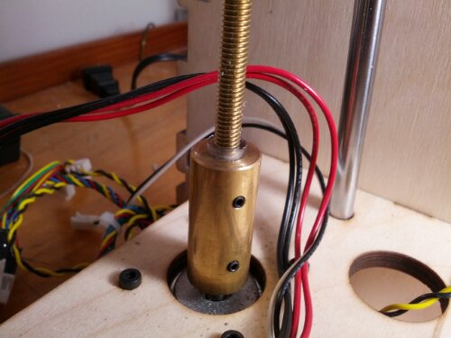
Then I tried the original pb wood couplers with surgical tubing.
Then I tried some CNC’d aluminum couplers I bought on eBay for surprisingly little.
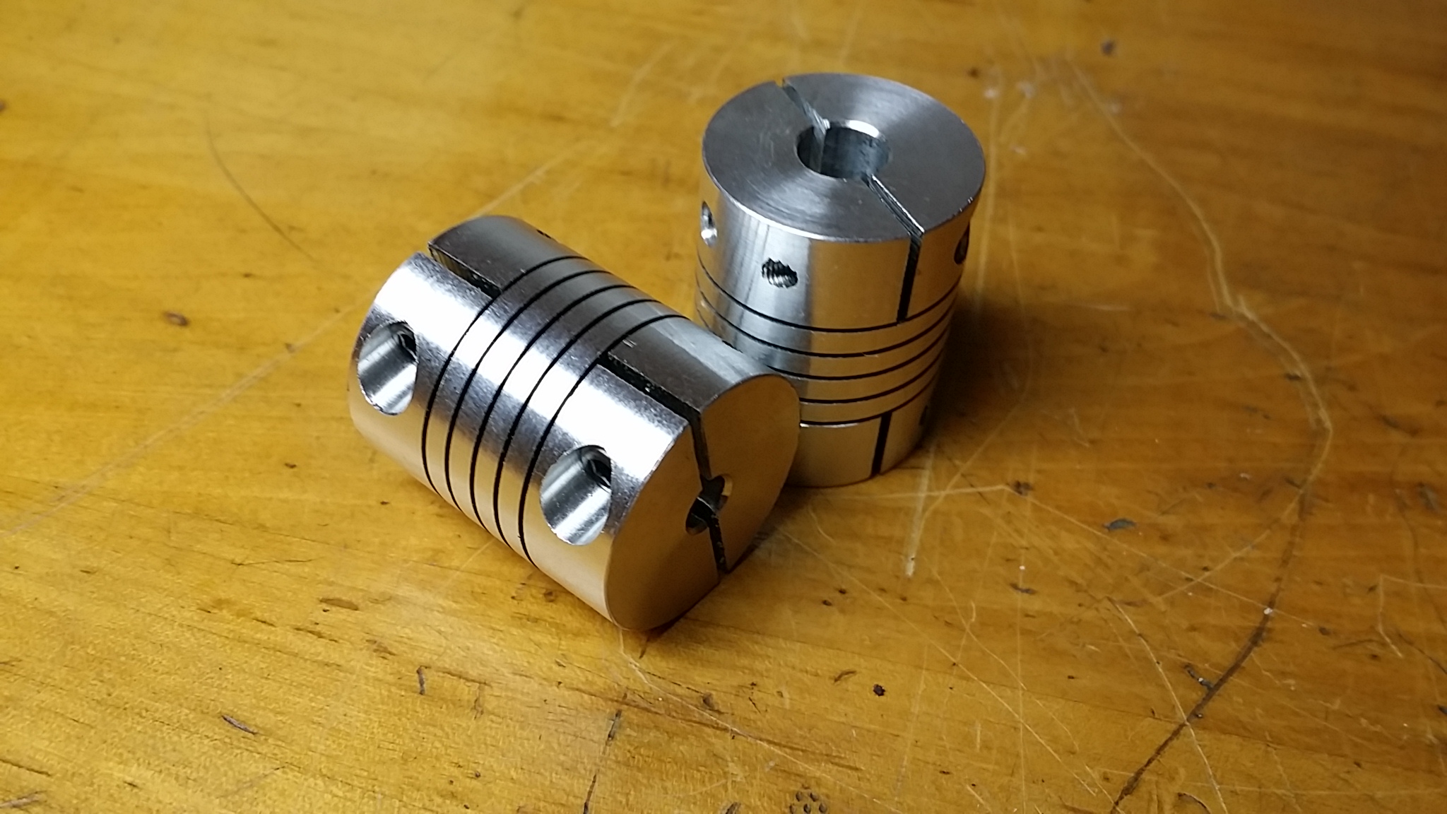
It’s worth mentioning that some folks feel these couplers to be of the wrong sort for coupling motor shafts to threaded rods in 3d printers of the most common designs. The reason being that if the motor shafts and threaded rods are secured in the couplers but not butting up against each other in the middle, then these couplers can actually flex longitudinally (they’re cut like a beefy spring), something that could conceivably introduce some imprecision into the layer height.
This is not even a theoretical problem if the couplers are not load bearing (like if additional bearings are used to take the weight off the motor shafts – probably a good thing assuming the trade offs are not too detrimental) or if the shaft and threaded rod are butted up against each other so as to eliminate the possibility of longitudinal flex in the downward direction (if the motors are on the bottom, one assumes that the weight of the gantry itself is sufficient to keep them from flexing upward). It’s also worth mentioning that LOTS of folks use these with good results.
Then I went back to my custom brass couplers, but with additional grub screws for even greater rigidity (it’s clear by now that I didn’t really understand the problem, right?).
Somewhere along the way I decided what I really needed to do was just get my threaded rods and my guide rods properly aligned. In pursuit of this dream, I reamed out the holes for the bolts securing the aluminum blocks (for the guide rods) at the top of the bot, did the same for the holes for the bolts holding the little donuts in place for the threaded rods at the top of the bot and also the holes for the M3 screws holding the Z motors in place. I had more adjustability than I could possibly figure out what to do with and wouldn’t you know it? I couldn’t figure out what to do with it.
I aligned the guide rods as precisely as I could from the bottom of the bot (where they are fixed/non-adjustable) to the top of the bot (there wasn’t a lot of room for adjustment since the gantry is a pretty tight fit at the top) but then I couldn’t for the life of me figure out how to really precisely align the threaded rods to match the guide rods AND the alignment of the rods and rails in the gantry. I was starting to go a little nuts, but let’s just stick to my 3d printer woes for now.
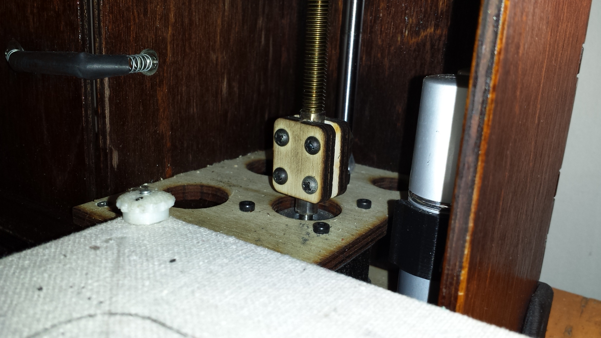
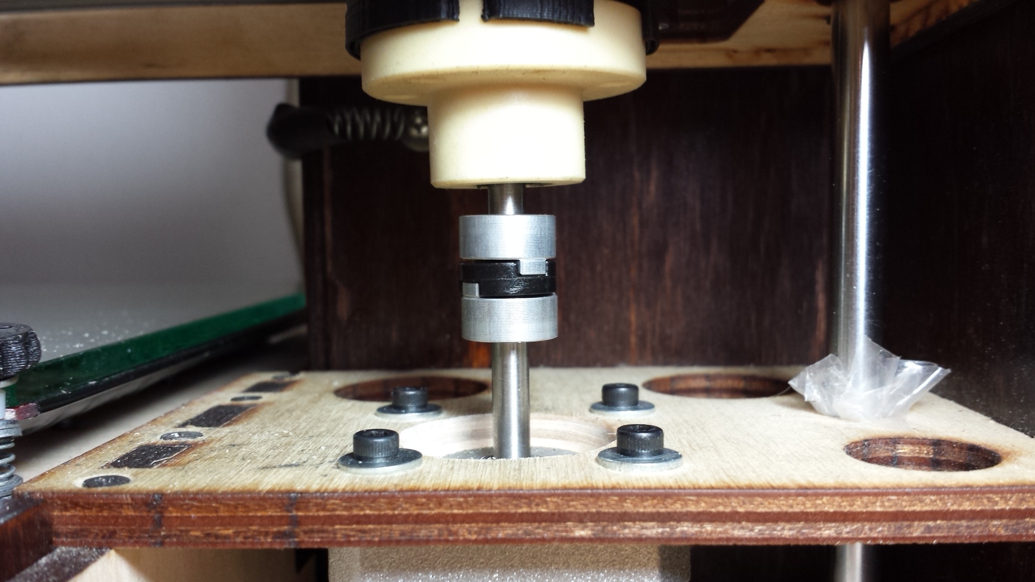
So finally it dawned on me that what I really needed were Oldham couplers (couplings? are these words interchangeable?).
Oldham couplers allow two shafts to couple to each other even if they are offset from each other. These would not a great solution for a bot with threaded rods that are not constrained at the top in my opinion, because there’d be nothing keeping the couplers from just slipping out of engagement with each other, but for the Printrbot GO, these seemed like a great idea.
So I toyed with the idea of actually making some. I figured I could machine the top and the bottom portions and print the little perpendicular guiding portion for the middle part and after, oh, maybe ten or twelve hours of work I could probably have some reasonably functional Oldham couplers. Then I thought, “Just for the heck of it, why don’t I see if I can find some for a reasonable price?” Amazon had some that were the perfect size for like eight bucks a piece.
And you know what? They work great. Scratch that. They worked great for a little minute and then began to suck. Hard. See next post.

***
It may be worth mentioning as an afterthought that there are a couple of compounding design elements of the Printrbot GO gantry that I believe contribute to the problem of Z wobble for this bot:
- The threaded rods are not in line with the guide rods (they are a centimeter or two forward of the rails) nor are they centered with respect to the center of gravity of the gantry. This causes the gantry to sort of lean back a little and makes it’s vertical motion especially sensitive to irregularities in the threaded rods or their nuts. This problem seems to have been addressed at least in part in the designs of the new bots in the GO family.
- The gantry is arguably under-constrained with only one LM8UU bearing on each side for the guide rods. This allows more rocking in the gantry than might otherwise be present if at least one side had two sets of bearings spaced as far apart as the design might allow. I’m not sure if this is a mod I’m likely to attempt since the additional bearing mount would require a VERY stiff connection to the rest of the gantry which would no doubt involve a lot of architecture and presumably additional weight. I kinda think the results I’m getting now are “good enough”. For now.
Those aluminum couplers look fit for Tony Stark’s workshop. Great to see the Oldham couplers do the trick for you in the end. Thanks for sharing the process you went through to get there. The result speaks for itself.
Thanks Jon, the improvement has definitely reinvigorated my interest in the printing itself to some extent. Makes me want to start printing some horological models in fact. 🙂
Awesome! Spider couplers are great. You might investigate some anti-backlash leadnuts too. There’s a guy in Texas who makes amazing quality parts for reasonable amounts – don’t let the name fool you: Dumpster CNC. I believe they’re made of delrin, which is super strong and has lubrication properties within.
Thanks Nathan! To be clear, spider couplers are different still, being also couplers that allow for an angular offset between the motor shaft and the threaded rod (somewhat like those CNC aluminum couplers I tried, only smoother) as opposed to a lateral offset as provided for by Oldham couplers. Spider couplers can be used with threaded rods that are unconstrained on the tops.