So I had this fantasy that I was going to assemble the thing, do a bunch of “test prints”, perform a lot of calibration (I think that’s what you do with “test prints”) and then tear it apart and stain it. Sometimes things don’t happen the way we plan.

Wanting to make something for my wife, I found this keychain on Thingiverse. I wasn’t entirely satisfied with the font however (not entirely satisfied might be the theme of this post), so I dug into the “Write scad” module from whence it came and created a Write SCAD compatible version of my own DroidLogo font.

Not satisfied with the tremendous triumph of having created keychains, I also made some mods and upgrades to the bot, three sizable ones somewhat simultaneously.
I had been reading up on the problem of artifacts in the vertical surfaces of a print caused by trying to print in layer heights that do not correspond to whole steps of the motors. RetireeJay (in addition to having a great handle) has some very valuable stuff to say on the subject (as do others), so I highly recommend any would-be 3d printing folks read the whole thread, but basically, trying to make the 5/16th inch threaded rods that came with the bot play nice with the metric software means that you end up with only a few very specific usable layer heights if you want to minimize these artifacts.
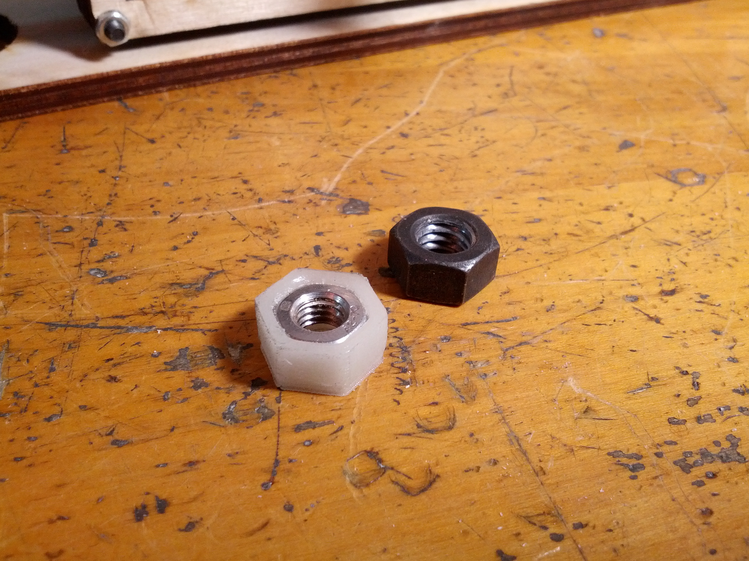
I was also not delighted with the surface finish or consistency of the threads on the stock rods and had misgivings about the fact that they were made out of the same material as the nuts (carbon steel plated with zinc). Mating the same material to itself is not a great idea when there’s going to be a lot of rubbing going on, so I wanted to swap out one or the other for a different material at a minimum.
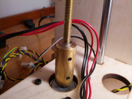
As an alternative, I decided to swap out the 5/16th inch threaded rods for some 6 mm metric treaded rods in brass and pair them with nuts in stainless steel. The rods have a thread pitch of 1 mm even, so this allows me to use any layer height that is a multiple of 0.005 mm, and that’s a restriction I can certainly live with. I decided on the harder material for the nuts because it’s much easier on the GO to change out the rods than the nuts, so if one of them is gonna wear out faster, I’d prefer for it to be the rods.
This modification required me to use the plastic tubing that came with the stock Z couplers as a spacer insider my brass couplers. I’m hopeful that the tubing may provide a tiny modicum of give as well, but realistically it’s probably not very much.
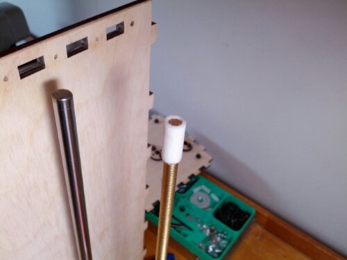
I also had to add some spacers for the tops of the rods to fit into the larger holes in the wood donuts, so I cut some out of PTFE to insure minimal friction and wear.
Last but not least I had to print some adapters to fit the smaller metric nuts into the nut traps built into the bot. Luckily, some kind bloke had already done most of the heavy lifting to create these parts, so I could just borrow his OpenSCAD files from Thingiverse and modify them for my simpler purpose. My un-calibrated bot spit them out pretty far from the dimensions I needed them to be, so I had to do some hand filing to get them to fit.
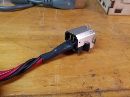
Another big mod I tackled at the same time was wiring up an X-box 360 power supply. The PSU that came with the bot only puts out about 6 amps and I had come to understand that if I wanted to run the heated bed at temperatures suitable for ABS that something closer to 20 amps would be required. On a tip from Brook, I researched the X-box PSUs and found that the original version ran at 203 watts, meaning that it would put out something close to 17 amps (at 12 volts). Perfect.
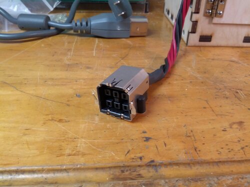
The only problem is that it uses a proprietary plug. Luckily, in addition to having plenty of these PSUs floating around, eBay also has X-box motherboards for sale, so I was able to pick up a couple “for parts only” examples for under $20. The tricky part was de-soldering and removing the socket from the motherboard without destroying it (thank god I didn’t have to worry about destroying the motherboard). I am NOT a skilled solderer, much less de-solderer, but following the instructions on this helpful website, I was able to finally get the twelve soldered connections (eight electrical and four structural) free and with enough of each of the leads for the positive and ground terminals intact to attach wires to them.
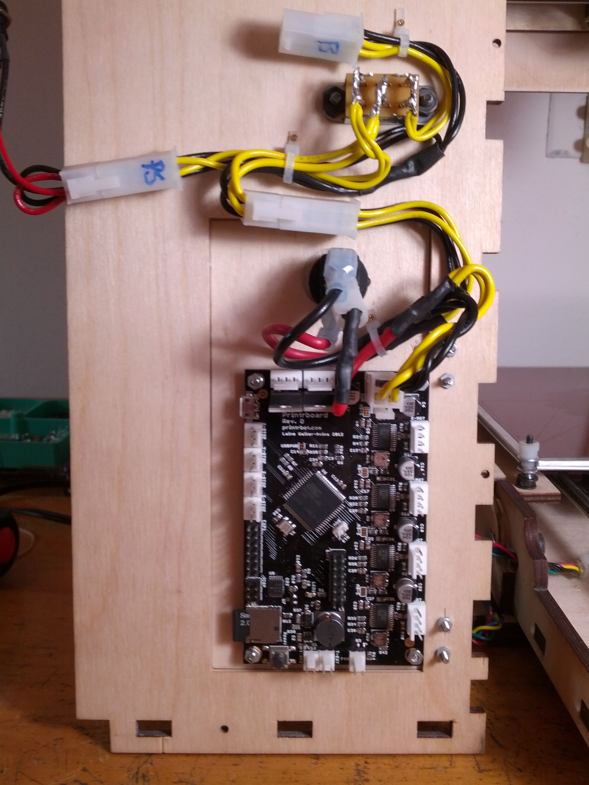
After soldering leads to the three positive and three ground leads (and dutifully heat shrinking them), the thing still wouldn’t supply any juice. Thankfully REPRAP SQUAD was on the case to inform me that the two additional leads have to be connected to each other before the PSU will supply power (apparently some kind of standby and/or safety feature). With those connected, the thing fired up.
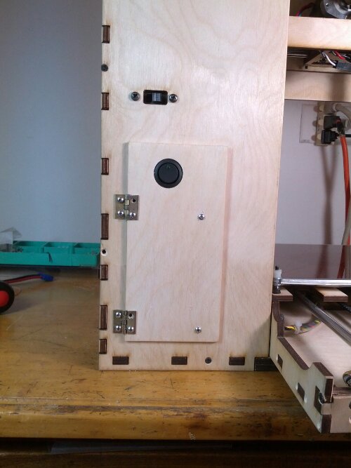
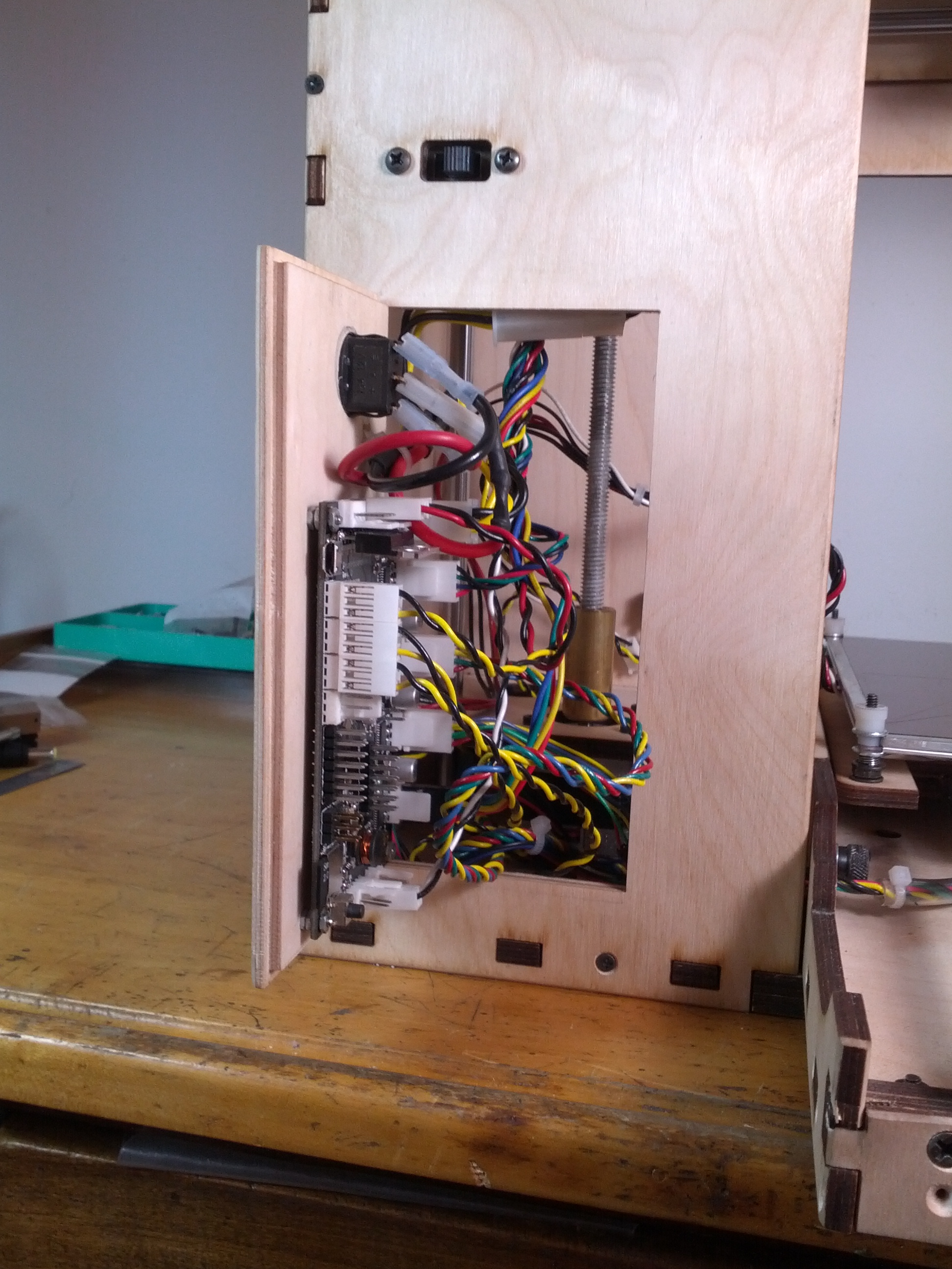
Last but definitely not least, I decided to add a front door to the bot to allow access to the electronics, and specifically the micro-USB port and SD card slot. The SD card on the printrboard allows one to initiate a print from the SD card and then untether the bot from the PC. A very cool feature, but significantly compromised by the fact that it is VERY slow to download files to the SD card while it’s inserted into the slot on the board, so you really want to copy files to it while the card is plugged directly into your PC and then transfer the card to the bot to start the print. The problem is how to do this when the motherboard is tucked away inside the box. The answer is of course to install a door.
I used one of the discarded (slightly warped) panels that the printrbot team had replaced for me which allowed me to cut a door with a milled recess for a nice clean fit. I still have to crapify (oxidize) the hinges and screws and figure out a latch however. I’d love to install an ancient looking lock mechanism (with a key and stuff), but I’d need it to be pretty low-profile to fit and so far I haven’t found anything close.
I’m thrilled with the added functionality and would highly recommend this mod to any GO owners.
And with that, I began to print with ABS.
Awesome. Good call switching to metric threads and going with brass for the rods over the bolts. It will be interesting to see how they fair over the long term.
Nice build. You definitely spent the time to do it right , keep up the good work.
Thanks! It’s been a steep learning curve but made a lot more manageable with help from folks like you!