So I’ve gotten totally out of sync between the building and the writing. I guess that’s what happens when you obsess over one and neglect the other, so let me try to catch up a little bit.
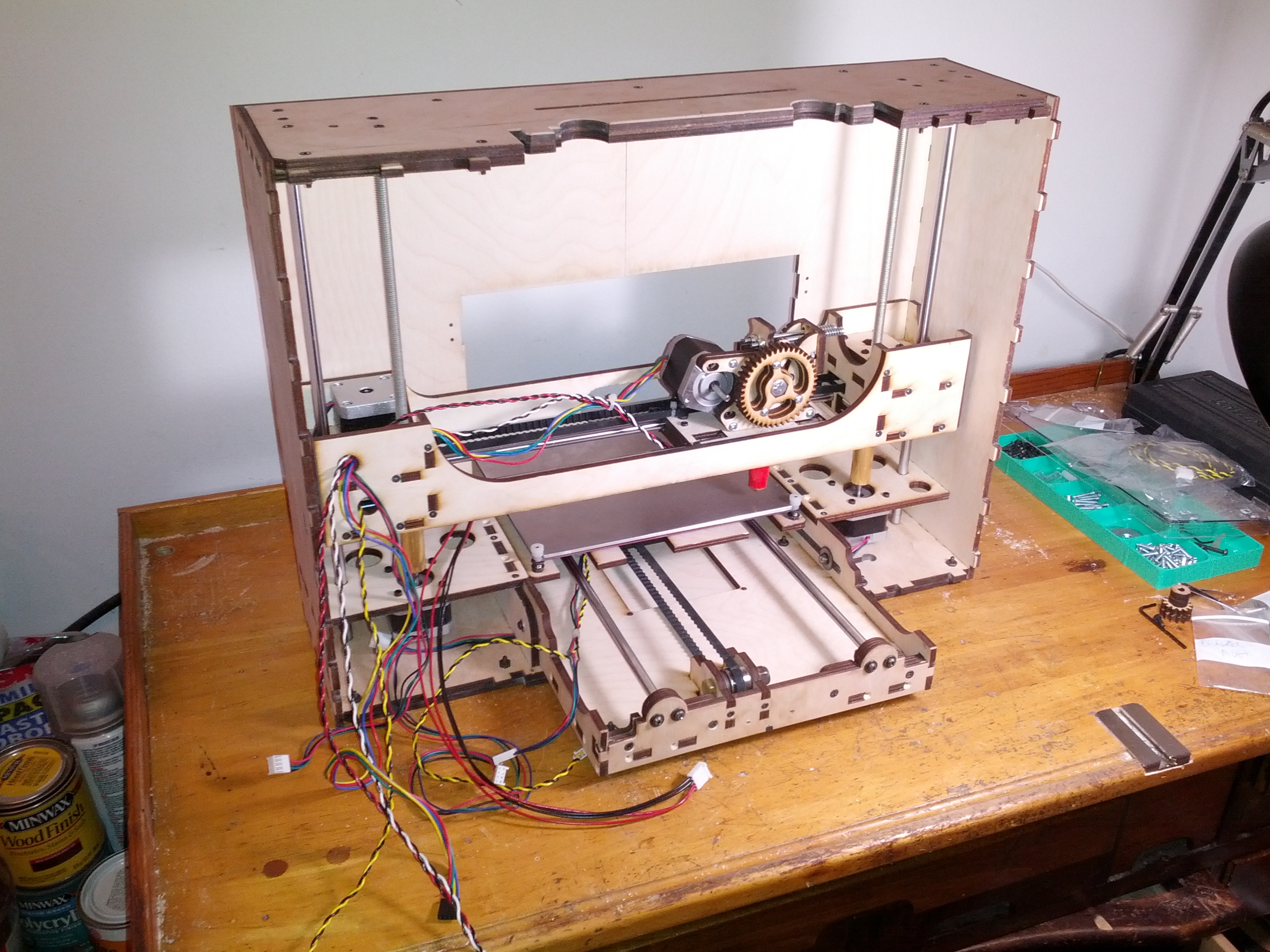
There were a few critical pieces missing from the kit as received. Most critically, the Z couplers were nowhere to be found. These are the pieces that connect the shafts on the motors for the Z axis to the threaded rods that move the entire X assembly (and extruder) up and down. Essentially, you put some plastic tubing over the motor shafts and then clamp two small squares of wood to them and the threaded rods to couple them to each other. It’s not the prettiest solution, but apparently quite functional, and the printrbot faithful insist that the little bit of freedom of movement created by the plastic tubing is essential to proper functionality in fact.
The key thing to keep in mind here is that the portion of the structure that travels up and down along the Z axis is guided by the precision ground rods, and the threaded rods merely control the vertical displacement (NOT the alignment), so absent the possibility that the precision ground rods, the threaded rods and the motors are perfectly upright and parallel, having a little slop is probably a good thing.
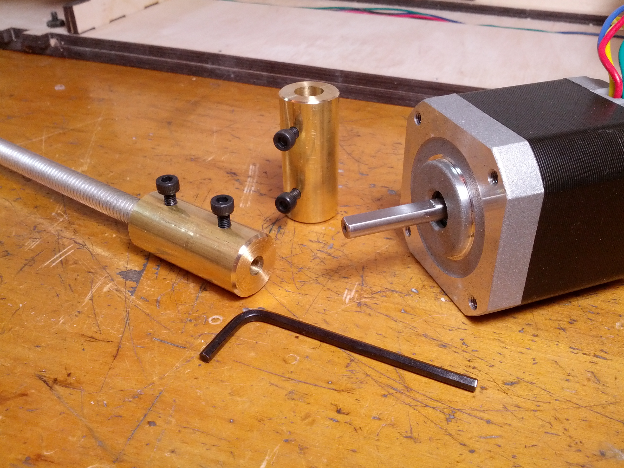
Well anyway, I did mention that these bits were missing, right? So I decided to make the couplings out of brass sleeves with some retaining screws. Oh yeah, and I bored out the brass tubes to within about 1/100th of a mm of the motor shaft diameter and the threaded rod diameter for minimal play. Likely possibility number one: binding will occur and slop will have to be introduced in some retroactive and ugly fashion (larger bore for the motor shafts with plastic tubing stuck inside?). Possibility two (less likely): the additional rigidity provided by the box structure combined with the precision laser cutting of the whole design will be precise enough that the precise and rigid couplers I made will actually be advantageous or at least not crippling. Here’s hoping.
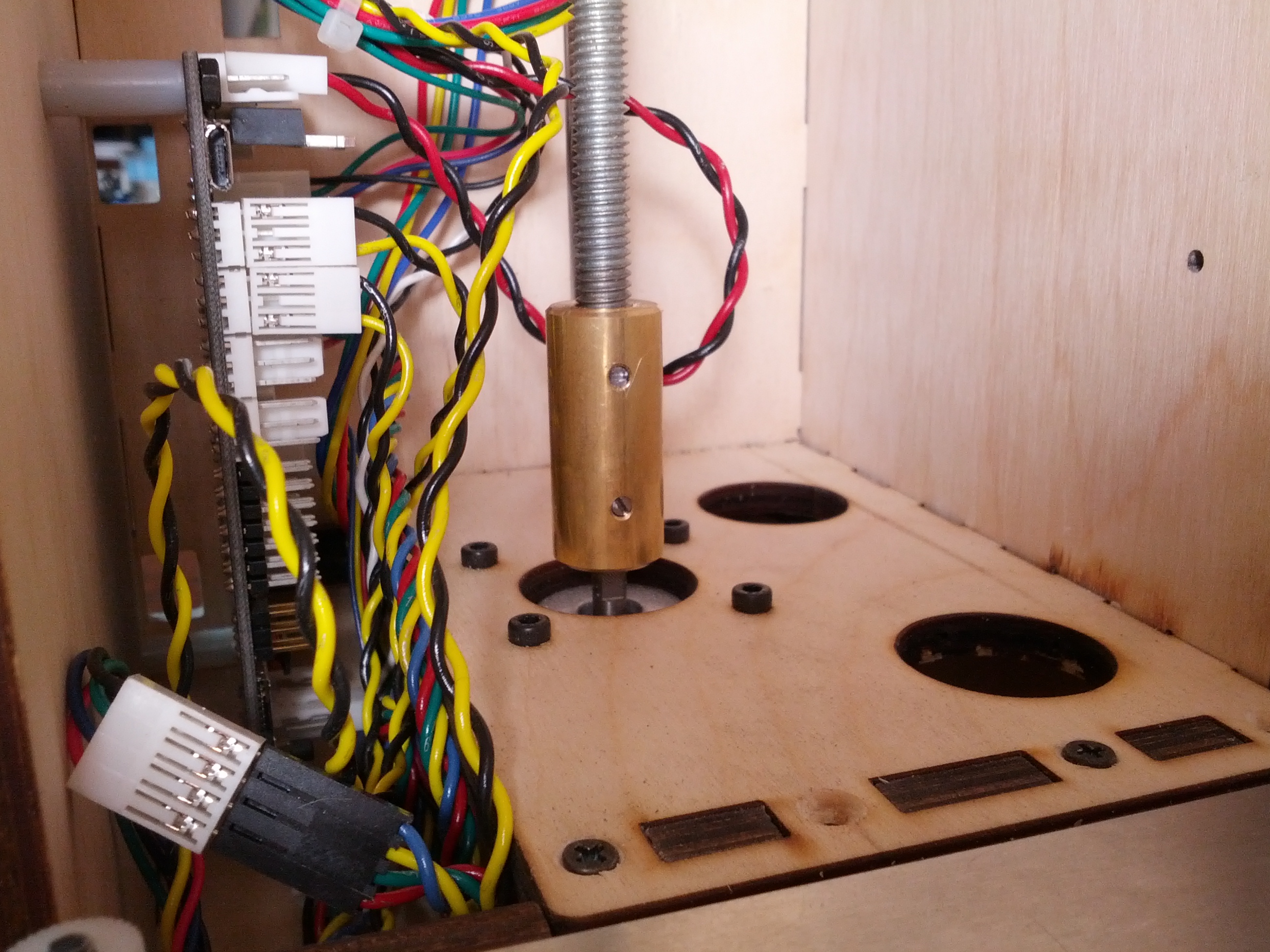
One other thing about those couplers, the one on the left side started making me nervous with the retaining screws sticking out and spinning around and the abundance of wires around (it’s like a rain forest of electronica in there). For now I’ve lopped the heads off the retaining screws and slotted them so that they’re fully recessed and won’t snag on any wires. The downside is that these now require a flat-head screwdriver and they are the only place in the build where that type of screwdriver is needed otherwise. Having a single fastener requiring its own tool seems like a terrible idea for a portable item like this (how large of a tool set do you want to drag around with you?), so I’ll have to rethink this later. Maybe recess the socket heads of the screws instead? I’ll figure something out. If I even keep these couplers that is.
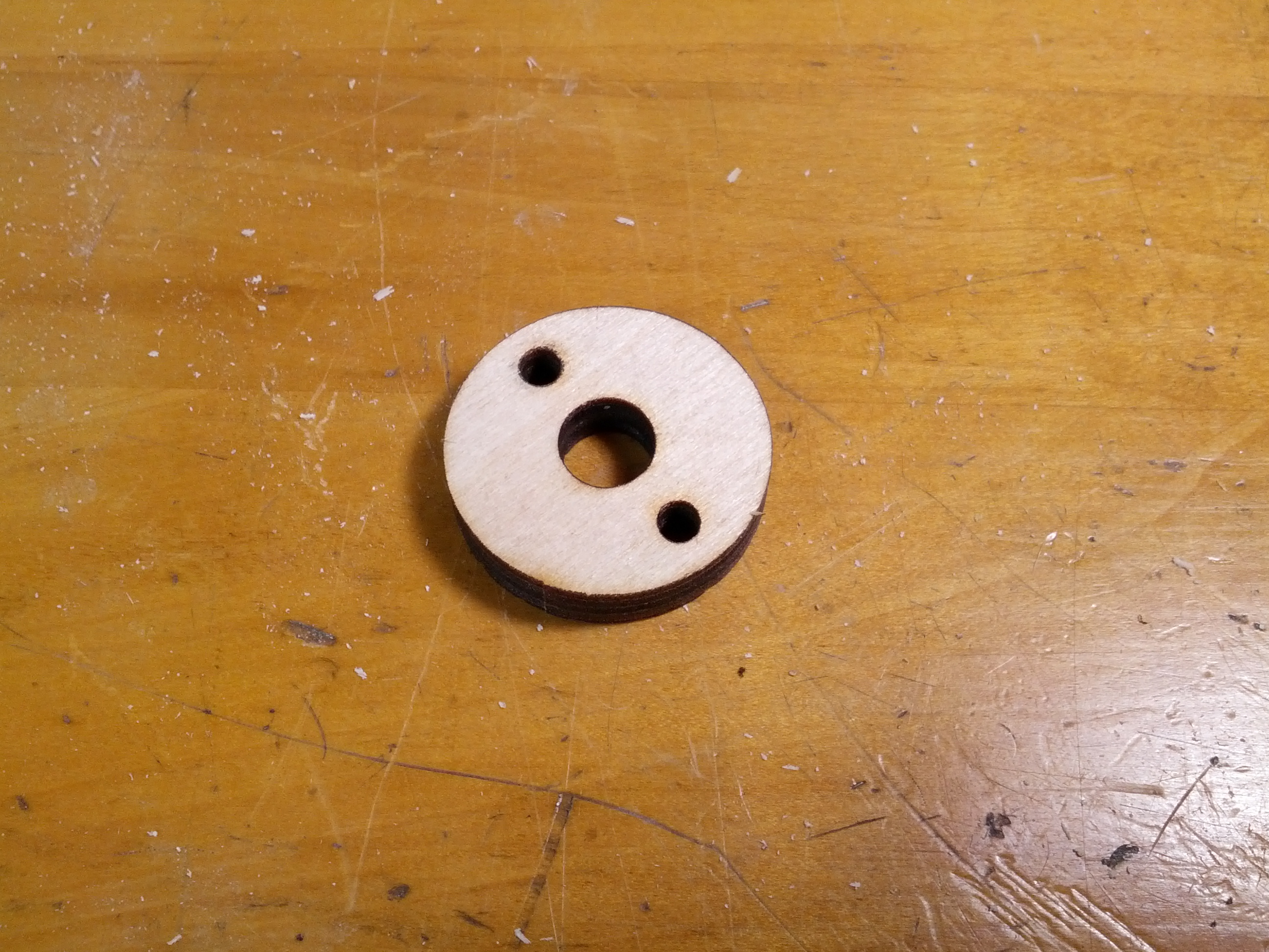
The other thing that was missing are two of these little donuts which serve as brackets for the Y rods, Z rods and Z threaded rods. Since the couplers I made allowed for some vertical adjustability, for now, I’ve just adjusted and locked them high enough that the threaded rods can rotate in the holes in the lower of the two top panels. Brook told me he’d send me a care package with the replacement print bed, lower top panel (tabs too short), Z couplers (I may still have to use them) and rod brackets, so I’ll insert those once said package arrives.
So next I get to play with the drawer action. Brook calls this one of the “tweaker” parts of the build (charmed by the choice of adjective) in the instructions when referring to the arrangement with the bolts/screws, nylock nuts, nylon bushings (or not) and large washers. These serve as the pivot point for the drawer when folding it up into suitcase mode and otherwise guide the sliding action when opening the bot up for printing. I think I installed these a little differently than Brook illustrated in the guide, but it works just fine all things considered (well, for now anyway, there’s no point in oiling the hinges until the damn thing is capable of printing something, right?). Every time I take out the drawer I rethink it a little, so not sure what I’ll ultimately settle on here.
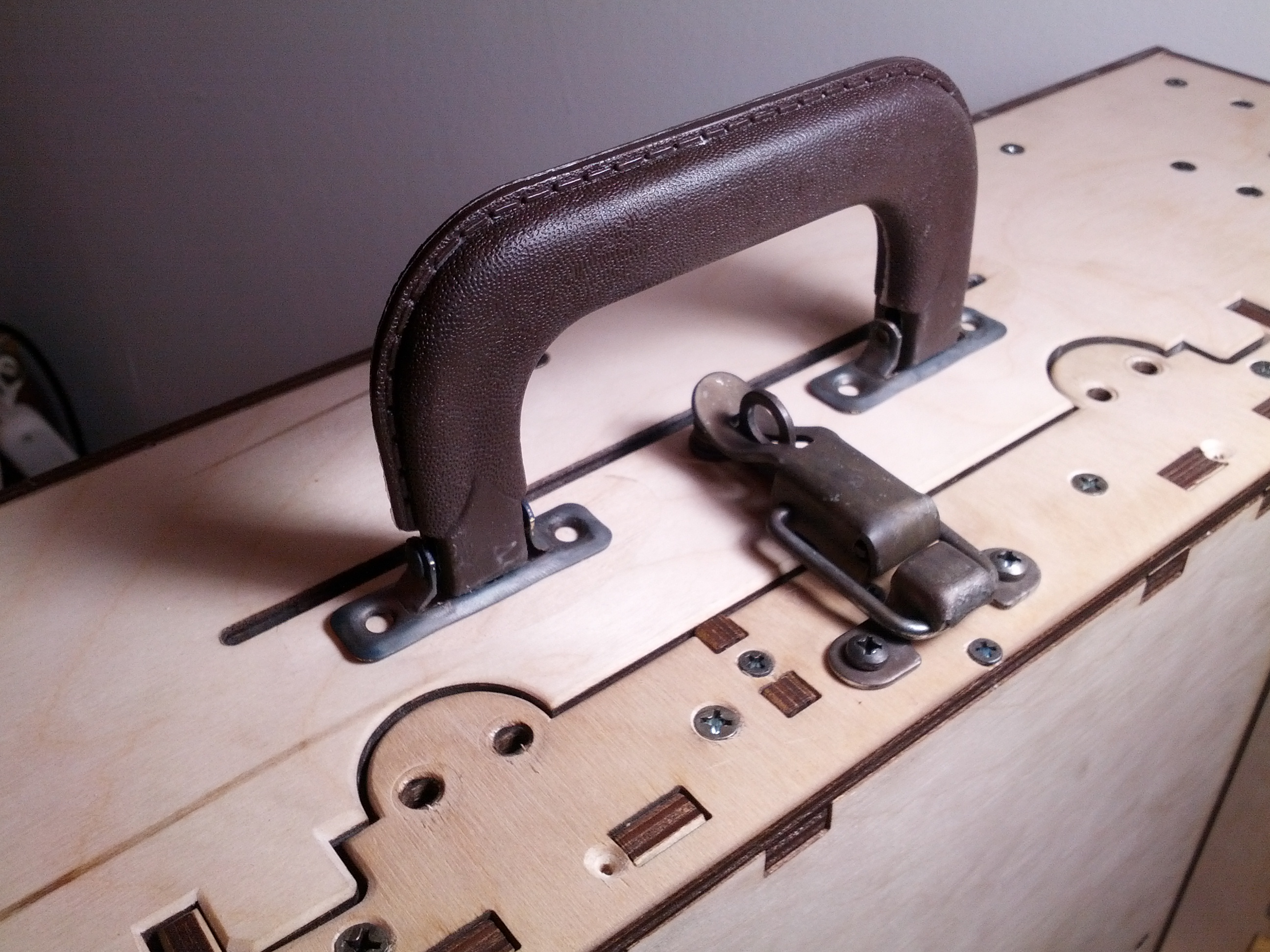
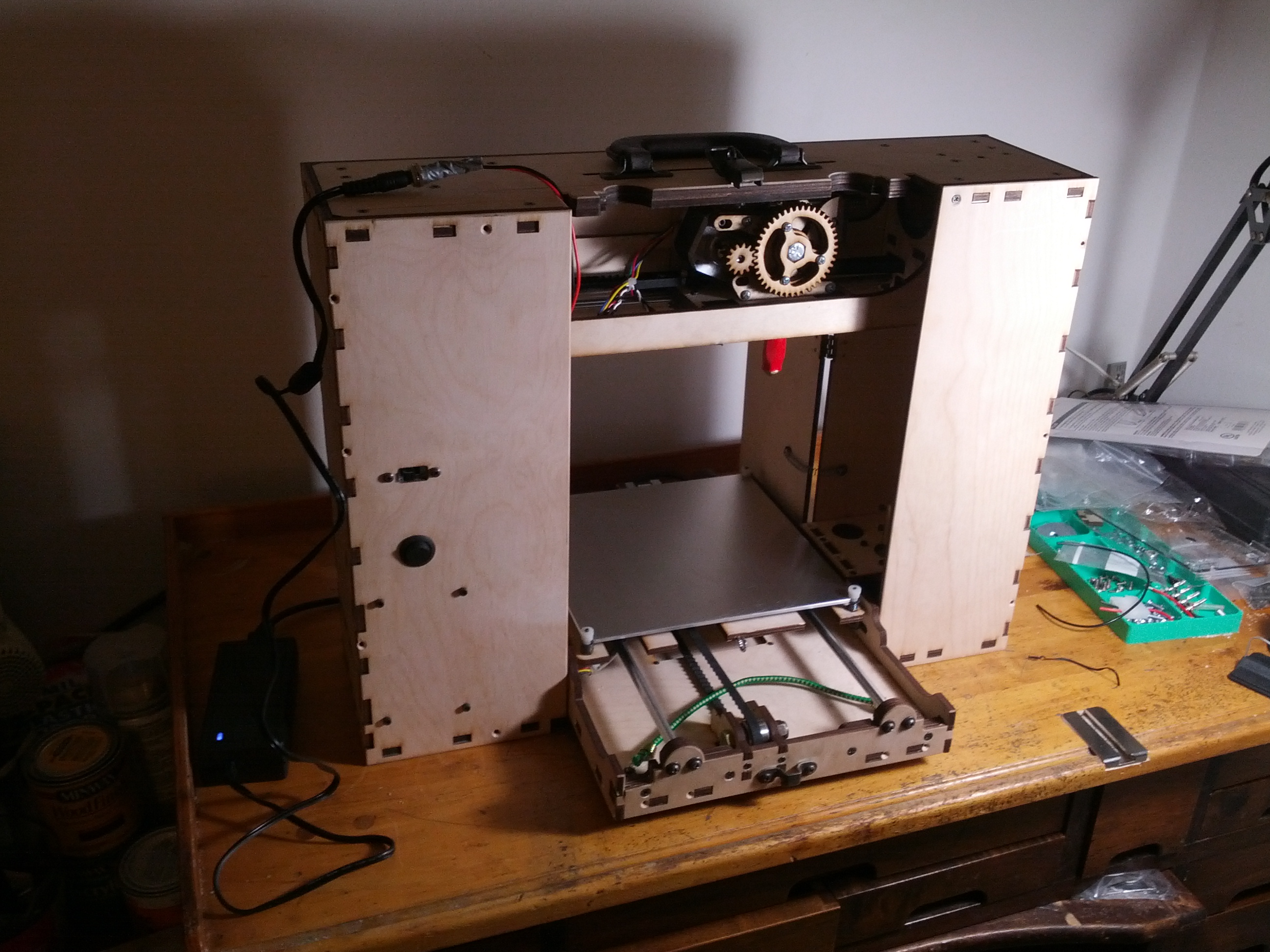
Next up came the latch and handle for the box, both of which I oxidized (old reliable gun blue) after using a sand blaster to remove the plating. It’s hard to say if the effect is steam punk exactly, or more like “I barely survived a three alarm fire”, but I kinda like it. The screws for the handle and for the latch potentially compromise the height of the printable build volume slightly, especially since I’d like to use screws with nuts for added stability. The problem being that the top of the extruder is right under the top panel when the carriage is all the way at the top of the Z rods, so I’ll have to file the tips off of the wood screws I used for the handle and consider milling recesses for the latch screws and nuts perhaps. Or maybe just cutting the very top off the extruder. Hmm.
When I finally got around to installing the doors on the back a couple small annoyances arose. For one, the seam for the doors doesn’t line up with the seam for the back panels. I don’t think this was a functional design decision (I could be wrong), so it seems like an oversight. A minor one admittedly.
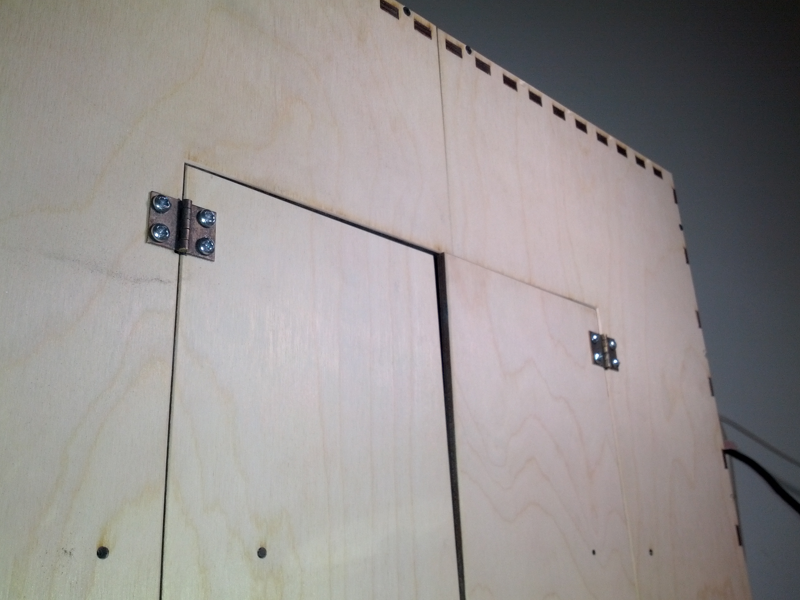
A more bothersome problem though was that the doors were warped, and in opposite directions no less. The one on the right sticks out at the top and the one on the left goes in a little. Grr. I may see if I can unwarp them using some of the voodoo techniques I read about on the internets. Seems a shame to throw them away and replace them.
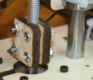
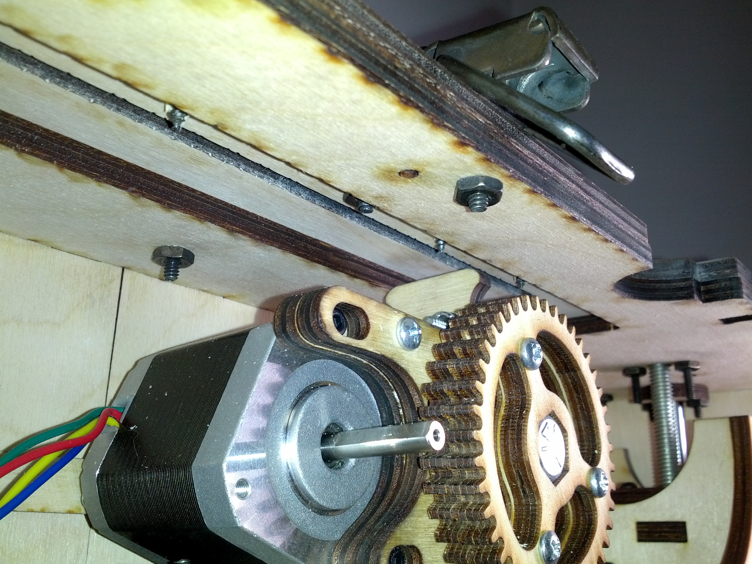
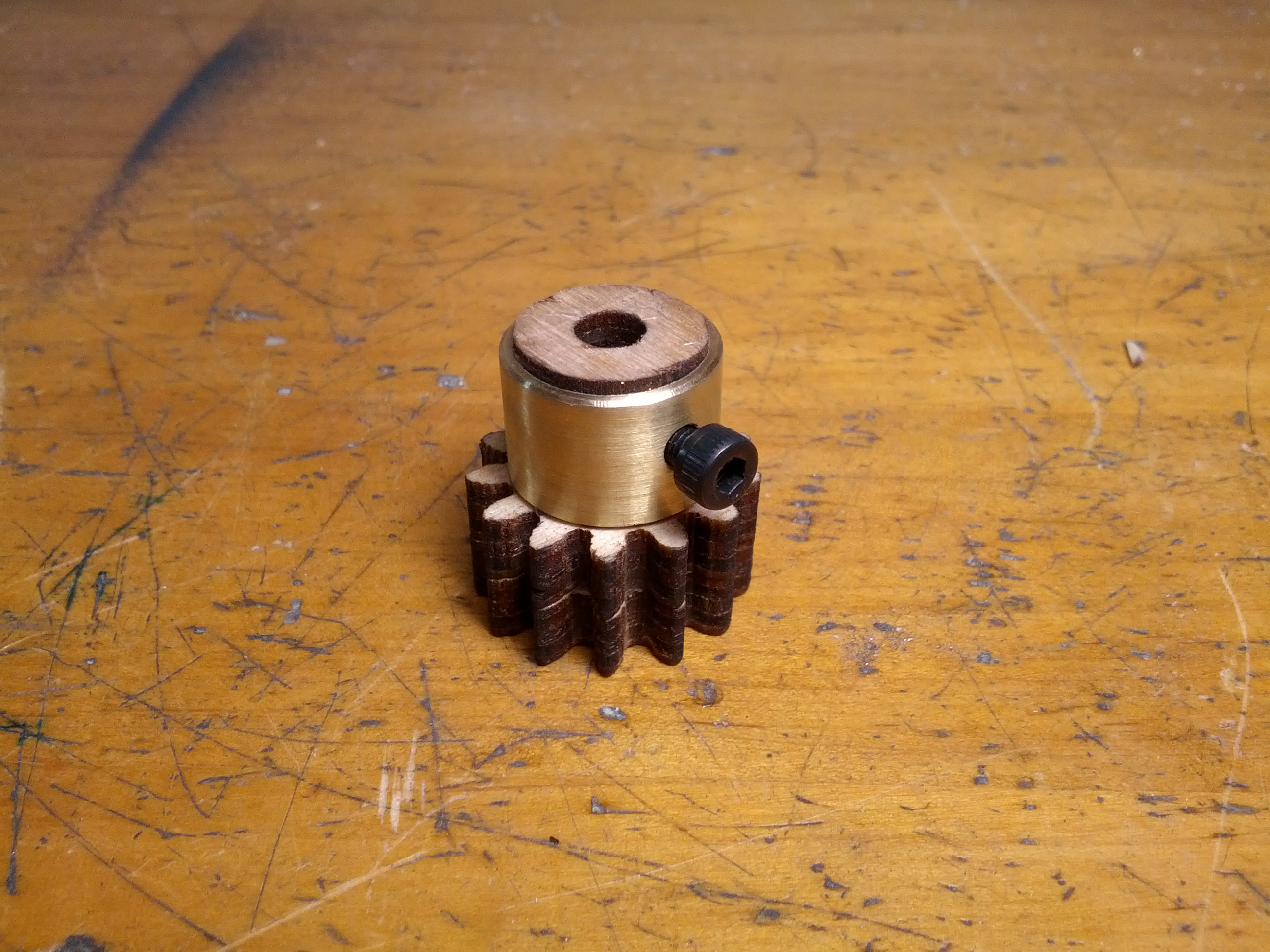
You’ll notice in the picture above of the extruder that the small gear is missing. That’s because I broke it.
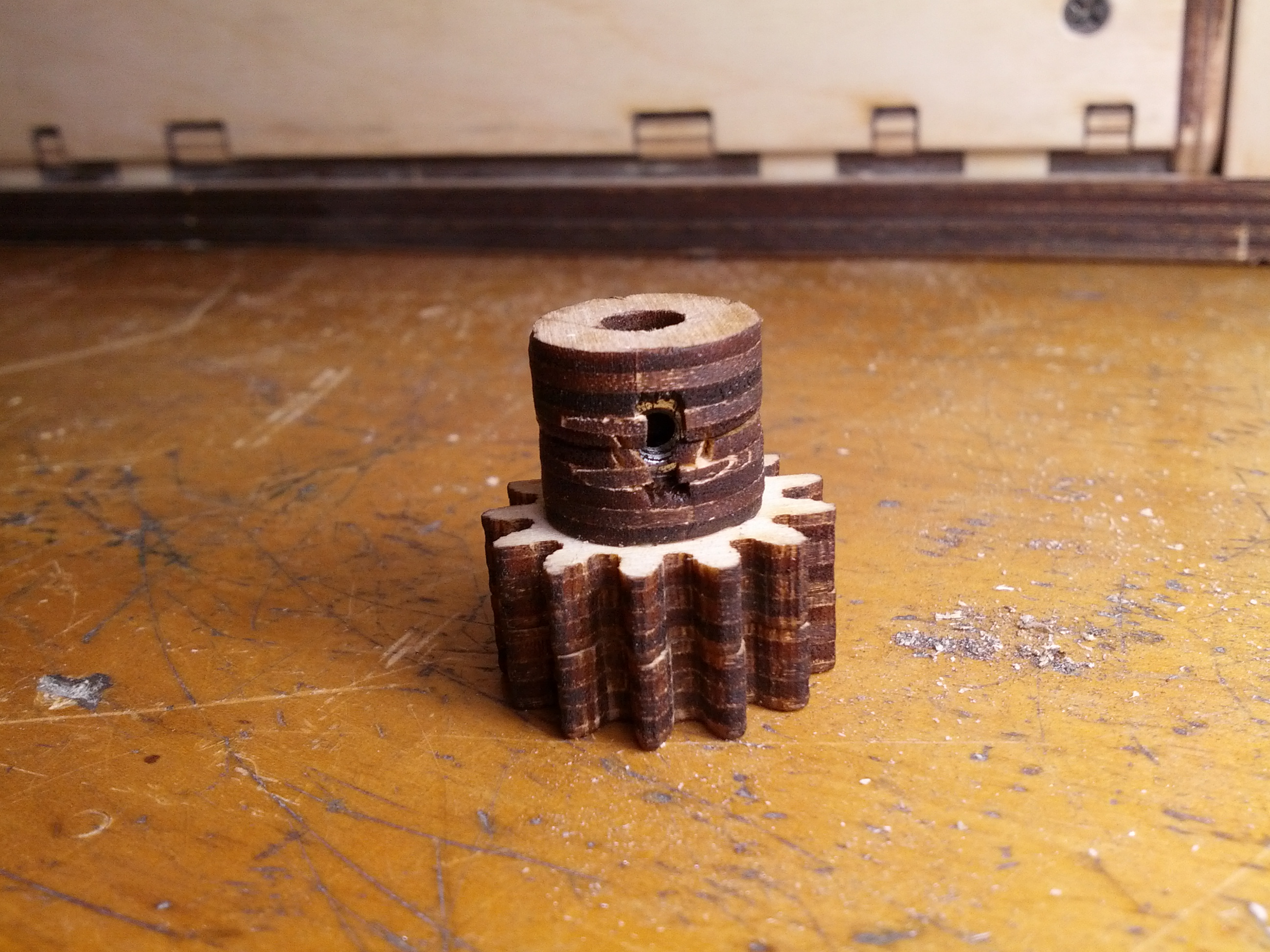
The set screw for the motor shaft threads into a trapped nut in one of the little wood rings and a little too much pressure will cause the nut to bust out the sides of the ring (not the most rugged design ever, but in all fairness the instructions do warn of very precise torque being required). Luckily I’m a handy guy so I was able to repair it and increase its robustness significantly by making a brass sleeve for it.
The next challenge on my plate was figuring out what to do with the wires for the Y axis motor and end stop. They have to come out of the drawer in a tidy fashion so that they won’t snag on the Y carriage when the bot is open and in use but also remain out of the way when you fold the thing up for travel. What I finally settled on was running them through the slot in the side of the drawer and cutting out a provision for them in the side support for the left side Z motor mount.
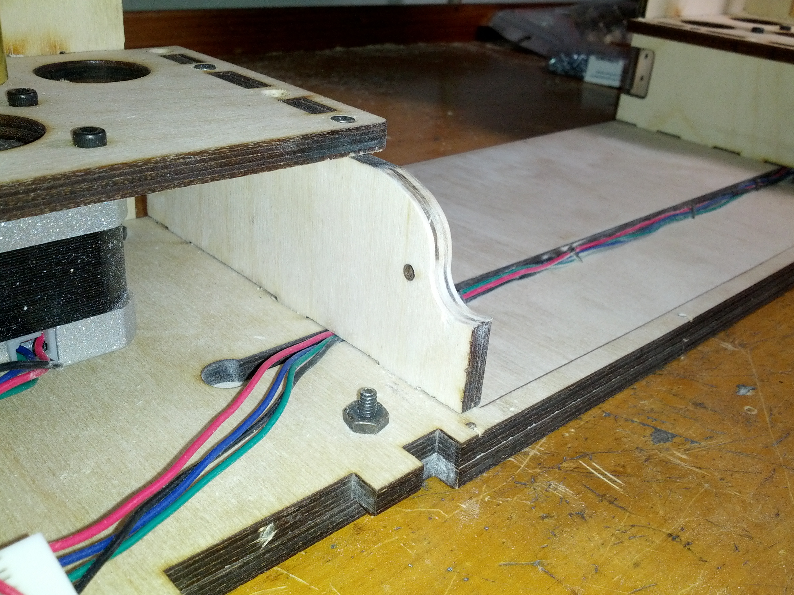
It’s tough to see exactly how this works without a video and even then it would be difficult to capture how fiddly it was to get it right, but after wrapping the wires with some tubing and tacking them down just so, they stay nicely out of the way of the carriage when the drawer is fully open and they fold up nicely when you pull the drawer out and close it up. Success.
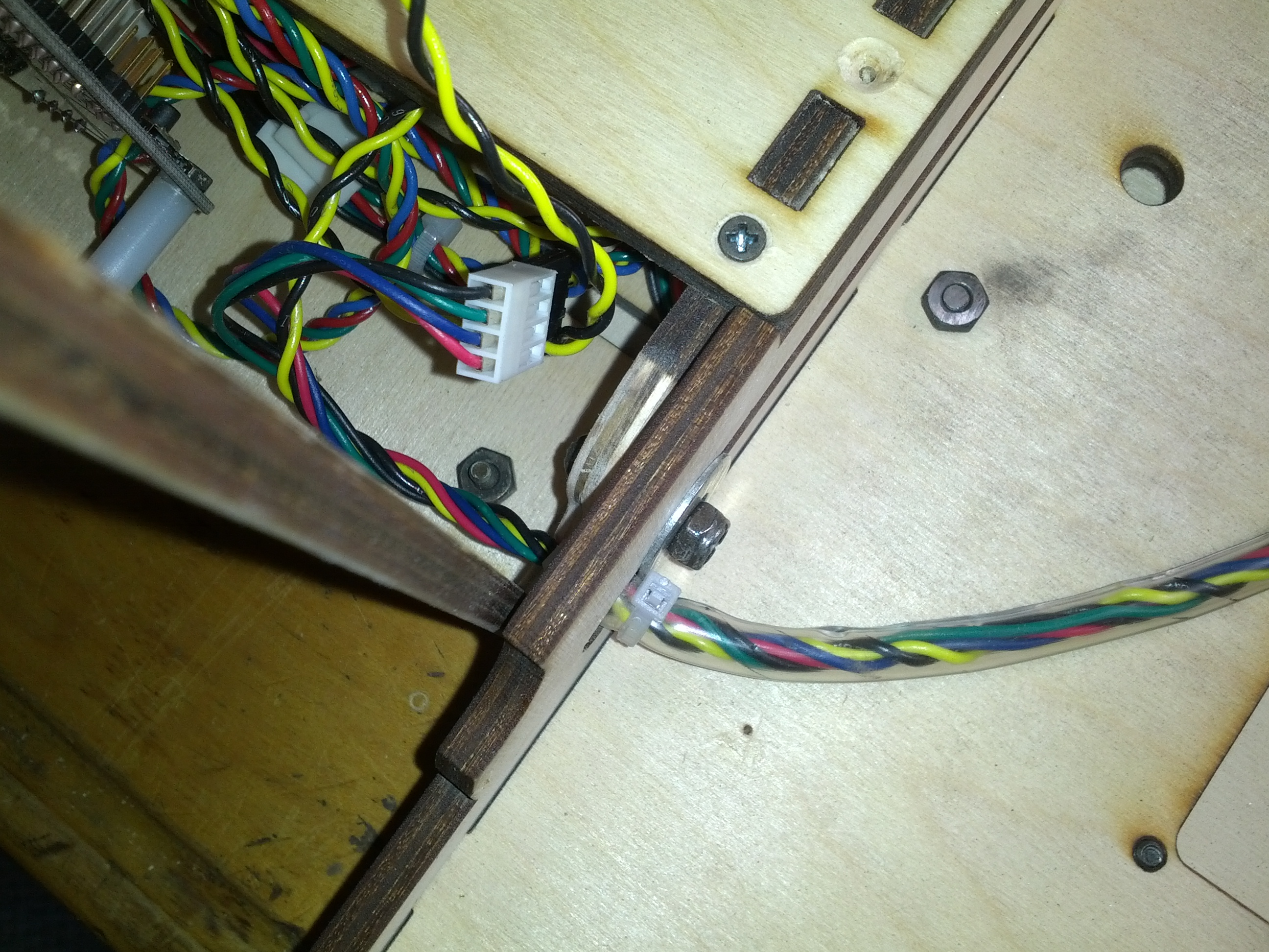
It’s just a happy coincidence that the slot in the side of the drawer extends beyond what is necessary for the pivot point, but I’ll take it.
Last but not least, I added a little bungee to keep the print bed carriage at the right height when closing the thing up. If the carriage is left loose, it slides all the way towards the motor side and gets in the way of the edges of the panels at the bottom of the bot when you try to pivot the drawer. While this is a minor annoyance when you’re closing the drawer, it actually keeps you from being able to open it without grabbing the carriage through the exposed crack in the partially open drawer or fiddling with it through the doors in the back of the bot. Not ideal and maybe not an ideal solution either, but this little hook and bungee solved the problem.
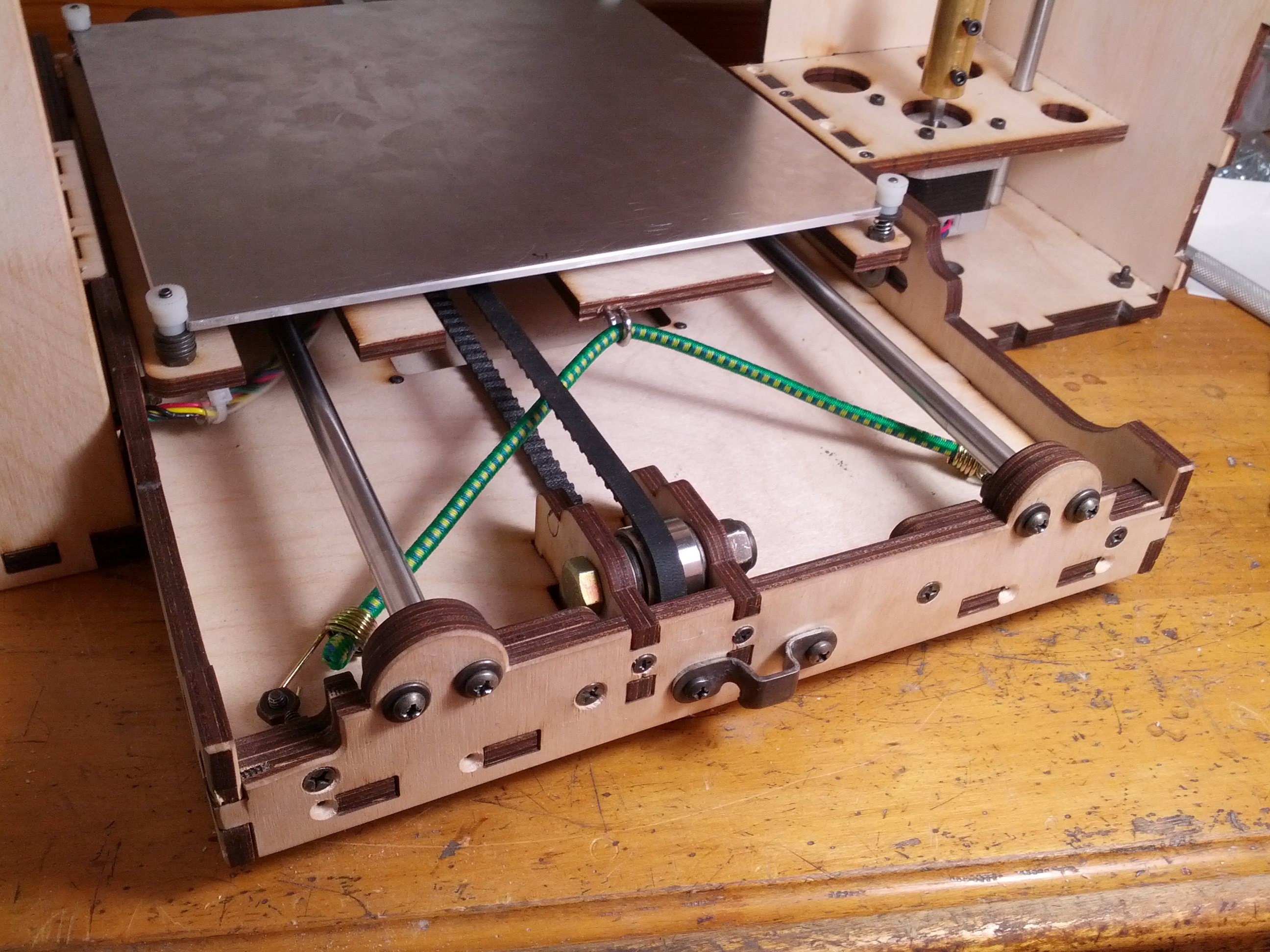
The bungee sort of flops around inside of the belt in a disconcerting fashion when its been released and the carriage is in motion (it’s screwed onto the inside of the drawer all permanent-addition-style), and while I don’t think it’s likely to actually cause a problem, when I take apart the drawer again to stain everything I plan to cut some little retaining slots for the bungee in the Y idler supports to keep it properly out of the way.
And then there was lots of wiring and re-wiring and re-re-wiring (mostly dealing with how to keep everything accessible AND out of the way inside the limited space) which I will not bore you with before I was left with the task of turning the thing on the first time. Exciting.
2 thoughts on “printrbot GO – the box (part two)”