Don’t just jump in here, start from Part 1!
So far we’ve got a single object in place with two tweakable variables and a little bit of basic OpenSCAD code under our belt. It’s time now to learn some new commands and a very handy new concept: the module. We’ll use rotate, union and a module call to add screw holes with head recesses to our drawing.
The first thing we’ll want to do is define a few new variables related to our screw dimensions and placement. Not knowing what kind of screws we’ll want to use, let’s leave the diameter of the screw holes and the diameter and thickness of the screw heads as variables: sSd, sHd and sHt (you there, in the back, no snickering!). But let’s also leave the distance from the edge of the object to the placement of the screw hole as a variable: e2s.
Now the first part of our code will look like this:
cSz = 20; //Overall size
tHk = 5; //Thickness
sSd = 4; //Screw shaft diameter
sHd = 6; //Screw head diameter
sHt = 2; //Screw head thickness
e2s = 8; //Edge to screw distance
pad = 0.1; //Padding used to insure manifold
The very powerful concept we’re going to explore next is that of the module. Because we want to duplicate our screw hole three times (once on each face of our object), rather than coding the same thing three times with different translation and rotation, why not save ourselves a little coding by making a screw hole module?
Before we do that, let’s just see what our screw holes are going to look like. To do this, let’s comment out all of our other code that contains rendering instructions. This can be done by simply highlighting all of the code you want to comment out and then selecting Edit – Comment (or Ctrl+d). The resulting code will look like this:
cSz = 20; //Overall size
tHk = 5; //Thickness
sSd = 4; //Screw shaft diameter
sHd = 6; //Screw head diameter
sHt = 2; //Screw head thickness
e2s = 8; //Edge to screw distance
pad = 0.1; //Padding used to insure manifold

//difference(){
//	translate([-tHk, -tHk, -tHk]) cube([cSz, cSz, cSz]);
//	#cube([cSz-tHk+pad, cSz-tHk+pad, cSz-tHk+pad]);
//}
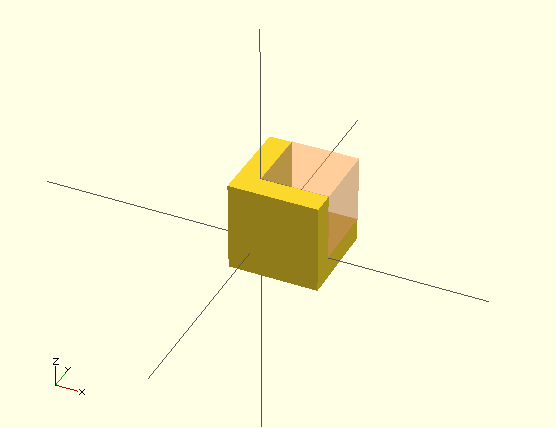
Commenting out code is a great way to remove something from your model temporarily so you can work on something else, but if you Compile and preview or Compile and Render at this point, you’ll get nothing, as there is nothing to render, only some unused variables declared. Instead, add this and then Compile and preview:
union() {
        cylinder(h = tHk+(pad*2), r= (sSd/2), center = true);
        translate([0,0,-(tHk/2+pad)])
        cylinder(h = sHt+pad, r = (sHd/2));
}
Let’s dissect what we’ve done here a little. We’ve created a union (a joining together) of two children (the children are separated by a semicolon). Child one is a cylinder that has a height (h) equal to the thickness of our protector plus padding (twice padding actually so that it’ll have padding for the inside and the outside of the thickness of our object). It also has a radius (r) equal to half of our screw shaft diameter and it is centered about the origin (we could’ve assigned it two different radii, r1 and r2 and then the cylinder would’ve been tapered accordingly; a pretty neat trick).
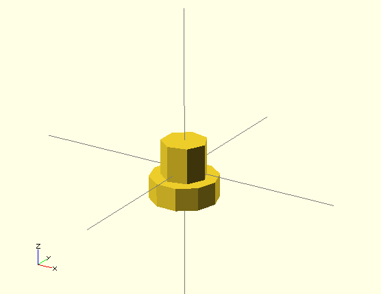
By default the circle that forms the cylinder is centered about the origin and pointing up, but the “center = true” command tells it that the height of the cylinder is also centered about the origin. Child two is a shorter, fatter cylinder with a height equal to our screw head thickness (plus our padding) and a radius equal to our screw head diameter divided by two. We’ve also translated this second child down the z axis by half of our component thickness plus our padding. When these two children are joined into one object, they are vaguely screw like, just as we wanted.
Take a close look at the cylinders that make up our screw, notice anything interesting? The cylinder that represents the shaft of the screw has seven sides while the cylinder that represents the head of the screw has ten sides. That’s because we’re modeling with the default resolution settings in OpenSCAD, so a cylinder with a smaller radius is going to have less facets than a larger cylinder. This can be set independently for each curved shape if we want (using “special variables“), but I’m planning instead to set it for the entire project at a later time.
Now let’s turn this into a module and paste it into our code somewhere. You can put the module before or after the other stuff and remember to uncomment the other stuff, something like this:
cSz = 20; //Overall size
tHk = 5; //Thickness
sSd = 4; //Screw shaft diameter
sHd = 6; //Screw head diameter
sHt = 2; //Screw head thickness
e2s = 8; //Edge to screw distance
pad = 0.1; //Padding used to insure manifold

difference(){
	translate([-tHk, -tHk, -tHk]) cube([cSz, cSz, cSz]);
	#cube([cSz-tHk+pad, cSz-tHk+pad, cSz-tHk+pad]);
}

//Create screw holes
module screw_hole(){
	union() {
        cylinder(h = tHk+pad, r= (sSd/2), center = true);
        translate([0,0,-((tHk+pad)/2)])
        cylinder(h = sHt, r = (sHd/2));
	}
};
If you Compile this, you won’t see any screw holes yet, because the module has not been called anywhere. Let’s do that now. To remove the material related to our screw holes from the rest of our object, we’ll want to paste the module calls as children into our difference function, but we’ll also want to specify the position (translate) of the screws and also the proper rotation of the screw holes like this (this is for the screw hole in the plane parallel to the xz plane as noted in the comment):
//Add screw holes
translate ([e2s,-(tHk/2),e2s])
rotate([-90,0,0])
screw_hole(); //xz plane screw hole
The important things to remember about the rotate function is that it rotates about the x axis first, then the y axis and then the z axis, in that order. A positive rotation is in the clockwise direction and a negative rotation is counter clockwise (from the point of view of looking in the positive direction along each axis). We’ve moved our screw hole to a negative y position equal to half the thickness of our object because our screw hole module is centered and because our padding is built into our module, we don’t need to add it here. The translation in the x and z directions are equal to the edge to screw distances we specified earlier.
When we put in our other two screw hole calls also, our code looks like this:
cSz = 20; //Overall size
tHk = 5; //Thickness
sSd = 4; //Screw shaft diameter
sHd = 6; //Screw head diameter
sHt = 2; //Screw head thickness
e2s = 8; //Edge to screw distance
pad = 0.1; //Padding used to insure manifold

difference(){
	translate([-tHk, -tHk, -tHk]) cube([cSz, cSz, cSz]);
	#cube([cSz-tHk+pad, cSz-tHk+pad, cSz-tHk+pad]);
	//Add screw holes
	translate ([e2s,-(tHk/2),e2s])
	rotate([-90,0,0])
	screw_hole(); //xz plane screw hole
	translate ([e2s,e2s,-(tHk/2)])
	rotate([0,0,0])
	screw_hole(); //xy plane screw hole
	translate ([-(tHk/2),e2s,e2s])
	rotate([0,90,0])
	screw_hole(); //yz plane screw hole
}

//Create screw holes
module screw_hole(){
	union() {
        cylinder(h = tHk+pad, r= (sSd/2), center = true);
        translate([0,0,-((tHk+pad)/2)])
        cylinder(h = sHt, r = (sHd/2));
	}
};
The astute among you will notice that we didn’t need the rotate function for the screw hole in the xy plane, but I left it in rotated (0,0,0) just to make the code look consistent. When we compile all of that, it looks like this:
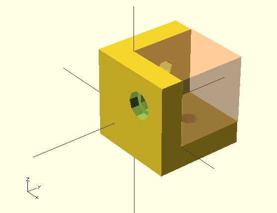
Phew. Next time we’re going to add fillets (rounded edges) to our corners. Yes, it’s gonna get dense; but don’t worry, we’ll take it one step at a time.
One thought on “corner protectors in OpenSCAD (3)”