Don’t just jump in here, start from Part 1!
So now that we have some screw holes in our protector, it’s time to make it pretty. As with many things in life, the last few steps that take the design from functional to aesthetically pleasing are a lot more work than the ones preceding them, but perhaps more fun to see come to life also.
A fillet is essentially a curved edge. As far as OpenSCAD is concerned, it’s helpful to think of creating this curved edge by subtracting from our object one quarter of the exterior of a cylinder for every straight corner that we want to add a fillet to. The size of our fillet is something that we may want to tweak later, and its appearance and most attractive proportion will depend on our object’s thickness to a large extent. Because of this, let’s create a new variable that represents the size of the fillet radius as a proportion of the thickness and also a variable that turns this into a fillet radius. I’m going to add these two lines of code between the declaration of the edge to screw distance (e2s) and the padding size (I want to keep all of the design tweak parameters in the same general area).
fPer = 80; //Percentage of thickness to make fillet radius
fRad = tHk * (fPer / 100); //Fillet radius
Now let’s work on our fillet module. To begin with, comment out all of the render commands (everything that’s not a variable declaration or part of the screw hole module) so that we have a clean slate to look at. Then enter these commands.
difference() {
    translate([-pad,-pad,-pad])
    cube([fRad, fRad, cSz + (pad * 2)]);
    translate([fRad, fRad, -(pad * 2)])
    cylinder(h = cSz + (pad * 4), r = fRad + pad);
}
What we’re doing here is creating a cuboid which is large enough to enclose one quarter of a cylinder that has a radius equal to our fillet radius and long enough to span one side of our object (with some padding). Then we’re subtracting said cylinder from this cuboid to end up with something like this:
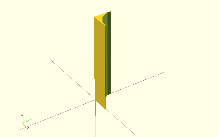
We want this to be a module however, so let’s do that the same way we did for the screw hole module.
module fillet() {
    difference() {
        translate([-pad,-pad,-pad])
        cube([fRad, fRad, cSz + (pad * 2)]);
        translate([fRad, fRad, -(pad * 2)])
        cylinder(h = cSz + (pad * 4), r = fRad + pad);
    }
}
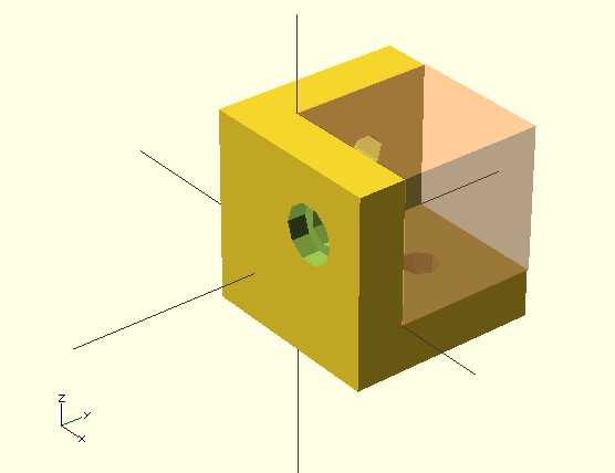
Now the only trick will be how to insert this into our previous code in such a way that it subtracts this fillet module from our object in the right location and the proper orientation. The first one (the corner that is parallel to the z axis and located at (-tHk,-tHk, -tHk)) is a piece of cake, because that’s pretty much how we aligned our fillet to begin with.
cSz = 20; //Overall size
tHk = 5; //Thickness
sSd = 4; //Screw shaft diameter
sHd = 6; //Screw head diameter
sHt = 2; //Screw head thickness
e2s = 8; //Edge to screw distance
fPer = 80; //Percentage of thickness to make fillet radius
fRad = tHk * (fPer / 100); //Fillet radius
pad = 0.1; //Padding used to insure manifold

difference(){
    translate([-tHk, -tHk, -tHk]) cube([cSz, cSz, cSz]);
    #cube([cSz-tHk+pad, cSz-tHk+pad, cSz-tHk+pad]);
    //Add screw holes
    translate ([e2s,-(tHk/2),e2s])
    rotate([-90,0,0])
    screw_hole(); //xz plane screw hole
    translate ([e2s,e2s,-(tHk/2)])
    rotate([0,0,0])
    screw_hole(); //xy plane screw hole
    translate ([-(tHk/2),e2s,e2s])
    rotate([0,90,0])
    screw_hole(); //yz plane screw hole

    //This here is the new stuff we just added.
    translate([-tHk,-tHk,-tHk])
    rotate([0,0,0])
    fillet(); //z axis fillet
}

//Create rounded edges
module fillet() {
    difference() {
        translate([-pad,-pad,-pad])
        cube([fRad, fRad, cSz + (pad * 2)]);
        translate([fRad, fRad, -(pad * 2)])
        cylinder(h = cSz + (pad * 4), r = fRad + pad);
    }
}

//Create screw holes
module screw_hole(){
    union() {
        cylinder(h = tHk+pad, r= (sSd/2), center = true);
        translate([0,0,-((tHk+pad)/2)])
        cylinder(h = sHt, r = (sHd/2));
    }
};
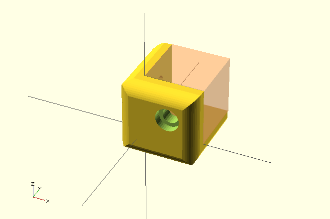
And the resulting object should look like this.
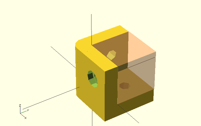
Now we just have eight more to place, and each of them requires more translation and rotation than that first one. Great. Don’t worry, I’ve done the figuring for you. I highly recommend though that you dissect a few of these placements and try to recreate them. I find it especially helpful to highlight whichever fillet I’m trying to place by putting the # sign before the fillet module call so that I can see where I’ve really put it (rather than where I intended).
cSz = 20; //Overall size
tHk = 5; //Thickness
sSd = 4; //Screw shaft diameter
sHd = 6; //Screw head diameter
sHt = 2; //Screw head thickness
e2s = 8; //Edge to screw distance
fPer = 80; //Percentage of thickness to make fillet radius
fRad = tHk * (fPer / 100); //Fillet radius
pad = 0.1; //Padding used to insure manifold

difference(){
    translate([-tHk, -tHk, -tHk]) cube([cSz, cSz, cSz]);
	   #cube([cSz-tHk+pad, cSz-tHk+pad, cSz-tHk+pad]);

    //Add screw holes
	   translate ([e2s,-(tHk/2),e2s])
	   rotate([-90,0,0])
 	  screw_hole(); //xz plane screw hole
	   translate ([e2s,e2s,-(tHk/2)])
	   rotate([0,0,0])
	   screw_hole(); //xy plane screw hole
	   translate ([-(tHk/2),e2s,e2s])
	   rotate([0,90,0])
	   screw_hole(); //yz plane screw hole

    //Add fillet edges
	   translate([-tHk,-tHk,-tHk])
	   rotate([0,0,0])
	   fillet(); //z axis fillet
	   translate([-tHk,-tHk,-tHk])
	   rotate([90,0,90])
	   fillet(); //x axis fillet
	   translate([-tHk,-tHk,-tHk])
	   rotate([-90,-90,0])
	   fillet(); //y axis fillet
	   translate([-tHk,-tHk,cSz-tHk])
	   rotate([0,90,0])
	   fillet(); //x axis z offset fillet
	   translate([cSz-tHk,-tHk,-tHk])
	   rotate([0,0,90])
	   fillet(); //z axis x offset fillet
	   translate([-tHk,-tHk,cSz-tHk])
	   rotate([-90,0,0])
	   fillet(); //y axis z offset fillet
	   translate([-tHk,cSz-tHk,-tHk])
	   rotate([0,0,-90])
	   fillet(); //z axis y offset fillet
    translate([-tHk,cSz-tHk,-tHk])
	   rotate([180,-90,0])
	   fillet(); //x axis y offset fillet
	   translate([cSz-tHk,-tHk,-tHk])
	   rotate([-90,180,0])
	   fillet(); //y axis x offset fillet
}

//Create rounded edges
module fillet() {
    difference() {
        translate([-pad,-pad,-pad])
        cube([fRad, fRad, cSz + (pad * 2)]);
        translate([fRad, fRad, -(pad * 2)])
        cylinder(h = cSz + (pad * 4), r = fRad + pad);
    }
}

//Create screw holes
module screw_hole(){
	  union() {
        cylinder(h = tHk+pad, r= (sSd/2), center = true);
        translate([0,0,-((tHk+pad)/2)])
        cylinder(h = sHt, r = (sHd/2));
	}
};
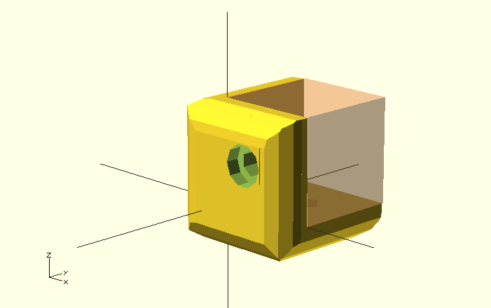
The thing is, at this point, the default rendering resolution of OpenScad makes our fillets look pretty crude. Remember the problem we talked about with regards to our screw holes? Let’s fix that now by adding these “special variables” declarations to the beginning of our code somewhere.
$fn = 0;
$fa = 0.01;
$fs = 0.5;
I can’t honestly say that I understand exactly what these variables do in concert with each other. I’m just relying on the recommendation of Brian Evans (remember that book I read?) and using $fs alone to adjust the resolution of my rendering. If you set $fs to 0.1 or so, you’ll get a VERY smooth looking render; if you set it to 1.0, it’ll be pretty crude. Leave it set to 0.5 for now and the results will look like this.
Next time we’ll try to round off the corners themselves and think about getting into real trouble with a big rounded fillet concentric with our screw holes for our final finishing touch. Well, that might take two more posts.
Thanks for that, great info!
The resolution managing variables $fa and $fs are afaik meant to override the fixed number of vertices $fn in a smarter way. (setting $fn to zero is not neccesary)
$fa gives the angle per polygon edge (and can be directly interconverted to an $fn value for big radii)
$fs sets a minimal edge length for small “circles” – the number of vertices becomes radius dependent
like so:
$fn(r) = min(360/$fa, C(r)/$fs) where C(r) = 2*pi*r
A reinplementation of this implicit and automatic internal function by the user can be useful in some cases.
The radius where modes swizch comes out to:
360/$fa = (2*r*pi)/$fs => r = 360/(2*pi) * $fs/$fa