Don’t just jump in here, start from Part 1!
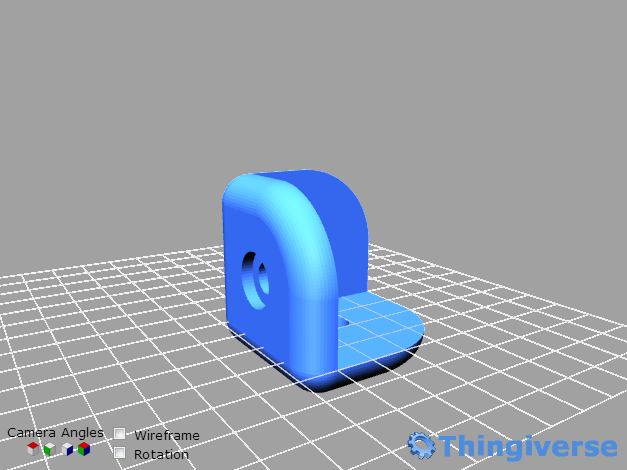
By the way, if you’re already convinced and serious about learning OpenSCAD, just Google “OpenSCAD tutorial” and you’ll find some great options out there. This is as much an exercise for me in “learning by teaching” as anything else. That said, anyone still left in the room can join me in making a “corner protector” (I seem to sometimes call it a “corner support” without rhyme or reason).
So to start making our corner protector, open OpenSCAD and enter (type or copy/paste) the following code into the lefthand pane and then hit F5 to render it.
cSz = 20; //Overall corner size
cube([cSz, cSz, cSz]);
We’ve done a few things here in two lines of code. We’ve created a variable “cSz’ defined as 20 units, we’ve included a comment about what that the variable means, and then we’ve used that variable to draw a cube. OpenSCAD is unit-less as a modeler, but slicers used in 3d printing will interpret the units as millimeters by default (this can be changed in the slicer). I’m a watchmaker, so millimeters are great for my brain by default too.
Variables names must include no spaces or other special characters (an underscore “_” is often used to separate two words in a variable, e.g “my_variable”). Otherwise, OpenSCAD’s variable declaration rules are, um, open enough to let you get yourself in trouble. For instance, you can create a variable called “circle” even though “circle” is a known 2d primitive used by the program. Don’t do that. It’ll make you nuts. Also, don’t make the variables so short that you can’t remember what they mean (typing a simple “x” everywhere is a great time saver while you’re writing the code the first time, but once you get up to five or six different variables, your chances of remembering what “x” means go downhill). I like to use short-ish abbreviations when writing the code and then sometimes go back (in a text editor) and use find/replace to turn all instances of that variable into something much clearer but that would have been more cumbersome to type throughout the code to begin with. In this example, I’m using “cSz” as an abbreviation for corner size and would likely change every instance of it in the code to “corner_size” once I’m finished.
You’ll notice that there is a semicolon after the variable declaration, followed by two backslashes. The semicolon indicates the end of the line of code and the backslashes tell the program that what follows is a comment. Each line of code much have a semicolon for the compiler to understand that you’ve reached the end of a complete thought. Comments are used to give yourself or anyone else reading the code a little context about what the heck is going on. In this case our comment is reminding us what the variable means.
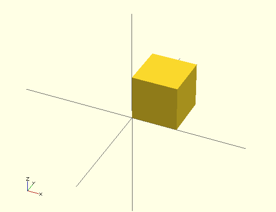
The second line of code actually renders a cuboid, that in this instance happens to be an actual cube (cubes by definition have the same x, y and z dimension; cuboids are not constrained in that way). It’s helpful to know that the cube we’ve created has one corner on the origin (the intersection of the x, y and z axes). Some shapes (like circles) will be centered unless otherwise specified, but cubes will align one corner to the origin by default. This is not obvious from the render however unless we turn on “Show Axes” from the “View” menu (or hit Ctrl+2). The result should look like this.
It’s helpful to know also that you can pan around within your drawing in the upper right pane (the render window?) by holding down the left button on your mouse, move the field of view by holding down the right mouse button and can zoom in and out with the scroll wheel (Mac users, you’re on your own here, I know you’re used to it – not completely on your own, Jon has a useful comment below).
I want the origin to represent the corner of the object that the corner support will be protecting though, so I’m going to move our cube off the origin a little bit and then also subtract another cube from it, like this.
cSz = 20; //Overall size
tHk = 5; //Thickness
pad = 0.1; //Padding used to insure manifold

difference(){
    translate([-tHk, -tHk, -tHk]) cube([cSz, cSz, cSz]);
    #cube([cSz-tHk+pad, cSz-tHk+pad, cSz-tHk+pad]);
}
We’ve done a lot here in a few additional lines of code. We’ve created two new vriables: “tHk” and “pad”. “tHk” represents the thickness of our protector/support and “pad” is a variable that we will use throughout the code whenever we are subtracting one object from another to maintain manifold.
The easiest way to think about manifold is in terms of water-tightness of a 3d model. If there are any small holes in your model, it’s not manifold. OpenSCAD likes to have a clear indication of where things begin and end, so if you subtract one cube from another and they both share a side (or two), the resulting object will not be manifold. Hence, always put a little padding between objects that are meant to be subtracted from one another. I’ve found it handy to sometimes adjust my “pad” to significantly larger than necessary while I’m designing the object just so that I can see better what is going on. Then I can set it to something quite small when I’m ready to render.
We’ve also introduced the “difference” and “translate” functions and how they can operate on children (stick with me here, I didn’t make this terminology up). “Difference” is a function that subtracts one object from another, with the two objects joined by curly braces “{}” and separated by semicolons (the two objects are the “children” in this case, and I’ve also indented them to make it more obvious what is being operated on). “Translate” is a function that moves an object by the amount specified in its arguments in the x, y and z directions. I’ve also included the pound sign “#” to tell the program to render the removed shape as a translucent object so I can see better what we’ve done.
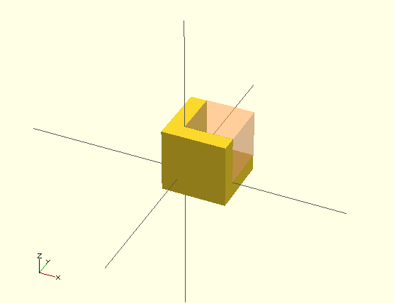
So what have we done? We’ve created a cube that is located (translate) off the origin by a variable “tHk” (negative “tHk” really) and then we’ve subtracted (difference) from that a cube that is located at the origin and is just large enough to make it clear where the borders of our object are. The results look like this:
Next time we’ll add some screw holes.
Offhand, Mac users can use two finger gestures & clicks for panning and zooming. They’ll also tend to need to use their keyboard’s function key (Fn) when hitting F5 to render, as Jobs was diametrically opposed to F# keys.
Thanks! Your comment now referenced in the post.