
I keep calling these GO corners because my plan is to print them out and attach them to the corners to make the Printrbot GO a little more travel sturdy. The truth of the matter is though, not even having the kit in my hands, much less the assembled bot, I have no idea if they’ll fit.
Not knowing the size that will be aesthetically pleasing relative to the overall size of the “suitcase”, the thickness that will be required to protect any switches or protrusions, how far from the edge the screws will need to be to have a secure hold on the wood nor what size screws I’ll be using, you could say this is something of a design challenge (well, you could say I should just cool my jets and wait ’til I build the damn thing, but you wouldn’t want to crush my charming enthusiasm, would you?). Thank god for parametric modelling.
I hope I’m not paraphrasing or misrepresenting the concept too badly when I say a parametric 3d model is one in which a certain number of design constraints are tied to variables rather than hard-coded numbers. If you want to design a rectangle with certain proportions but you don’t know what the actual size is going to be (or just want to leave it open to adjust later) you could describe it’s length as X and it’s width as X/2.) Or if you only need to insure that the width is a specific size smaller than X to fit some other design consideration, you could say the width is X-2.
For the purpose of only describing a rectangle, this is not all that helpful, but if that rectangle is the footprint of a complex design and we describe as many other dimensions as appropriate in terms of our original length X, we will then have a parametric model that can be scaled and tweaked by just changing our value for X.
The screen that greets you when you start OpenSCAD is not inviting. It’s downright cold in fact. Do not be dissuaded. I’ll walk you through a few things and it’ll start to make a lot more sense. 
If you are allergic to code, you might as well skip out now though, because a lot of what lies ahead in the next few posts is going to look like this:
length = 10
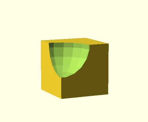
difference (){
translate ([length, length, 0]) cube ([length, length, length]);
translate ([length*2, length, length]) sphere (r = 0.6*length, center = true);
}
Trust me, this is going to make a lot more sense if we just dive in. If you have the tenacity to download OpenSCAD for yourself, follow along over the course of the next few posts and copy and paste the code along the way, I think you’ll get a decent picture of how OpenSCAD can be used to design complex objects in a manner that gives you a lot of freedom to tweak them after the fact. And for the purposes of 3d printing useful real world objects, this is an incredibly handy feature.
That snippet of code above renders like this by the way. Neat, right?
5 thoughts on “corner protectors in OpenSCAD (1)”