A lot of time has passed (four months) and a lot has happened since I last updated this blog. When I became fully committed to the idea of using end-stop-wired bed mounts for automatic bed compensation (basically when I figured out that it was viable) I got seriously sidetracked into the world of CNC machining in an effort to realize a more complicated and fabrication-intensive design for the mounts. For anyone already involved in 3d printing who is thinking about getting into CNC, let me warn you now: That way there be dragons. Although I may spill some considerable digital ink on the subject of semi-DIY CNC in the future, that is not the purpose of this post. This post is about the current evolution of my adjustable height, adjustable spring tension, end-stop-wired mounts for automatic bed compensation.
Just so we’re clear, the goal here was to implement a hardware solution for the feature that Marlin (the firmware I’m running) and most everyone else still calls “automatic bed leveling”. This term is wrong on a couple levels, but let’s step back even a half step further in case you haven’t been religiously reading this blog and have no idea what I’m talking about.
Getting a very clean, well adhered first layer is absolutely critical to getting good 3d prints. A lot of time and effort is generally spent making the bed as precisely “square” to the various axes of a 3d printer as possible to make sure that the first layer height is consistent across the platform to within a few hundredths of a millimeter ideally. Because this is such a frustrating process and somewhat difficult for manufacturers to guarantee from a purely hardware point of view (and forget about home built RepRaps and the like), the idea was introduced to probe the bed in various locations and just apply a correction in the software instead. If the far side of the Y axes is 1 mm higher than the near side, essentially you just tell the nozzle to climb 1 mm as it’s making a move from Y zero to Y max so that the bead of plastic laid down will still be nice and consistent despite that millimeter out of adjustment.
“Automatic bed leveling” is mostly automatic and it does involve the bed, but it doesn’t have anything to do with any part of the machine being level (perpendicular to gravity) nor does it actually change the alignment or position of any portion of the bed (as the word “leveling” would imply). This makes it not only wrong, but seriously misleading for newcomers and I have read more than a couple posts or questions in the past year or so from people breaking out their spirit levels in an effort to improve their prints. We can do better.
For awhile I was calling it “automatic tram correction” since the concept of a multi-axis machine tool being “in tram” was already a thing, but it’s been brought to my attention that this term, in addition to not being exactly analogous in the manner most commonly used by machinists (squaring the spindle to the bed), is not as universally known by machinists as I once thought. More critically, a more obviously descriptive term has been suggested that I’m on board with as well: “automatic platform (or bed) compensation” was thrown out there by Whosawhatsis on the Marlin GitHub and that sounds just fine to me, so you’ll now hear me referring to it that way instead. PLEASE JOIN ME IN USING “AUTOMATIC BED COMPENSATION” OR SIMILAR GOING FORWARD.
For Marlin to be able to calculate the plane of your print bed in order to perform the compensations necessary while printing, it needs to be able to probe the bed at multiple locations and determine the amount of Z offset between the locations. The most common ways to do that currently are to use a probe (a simple mechanical/electrical end stop switch on an arm next to the extruder was the most common approach initially, but more recently an inductive probe with a metal bed is being used with great success) or to place sensors under the bed so that the nozzle itself can be used as the probe. The method I’ve implemented (based on a suggestion by Whosawhatsis) employs the bed mounts themselves as end stop switches. When the nozzle probes the bed at each corner, one of the end-stop-wired mounts will trip (they’re wired in series) and Marlin will know what “Z=0” looks like at that location.
My initial experiments with this method convinced me of three things: 1.) It can work, 2.) the switches must be very consistent with regards to the pressure required to activate them and 3.) the switches must be independently adjustable to compensate for the varying amounts of flex in the carriage itself.
At the end of my last post on the subject I shared a picture of the third iteration of the compensating bed mount idea I was working on. When I installed one of these and started testing it, it became clear that it was not nearly as smooth and consistent as I wanted it to be.
The friction at the brass sleeve was increased dramatically by the fact that the bed was only pressing down on one side of the sleeve (causing the sleeve to want to tilt and bind), so it would’ve taken a LOT of spring tension to make it compress consistently. I modified it a couple more times but with the same results, so it was time to go back to drawing board.
I had been walking a fine line previously with regards to wanting to implement a bed compensation solution that might be practical enough that others would want to use it also. By the third iteration I’d already veered pretty far from the ideal of simple and practical, so I just decided to abandon that design goal completely and go for baroque. This is not in any way meant to discourage others from exploring a simpler implementation of this method. I’m pretty sure it can be done, I’m just not sure I’m the guy to do it.

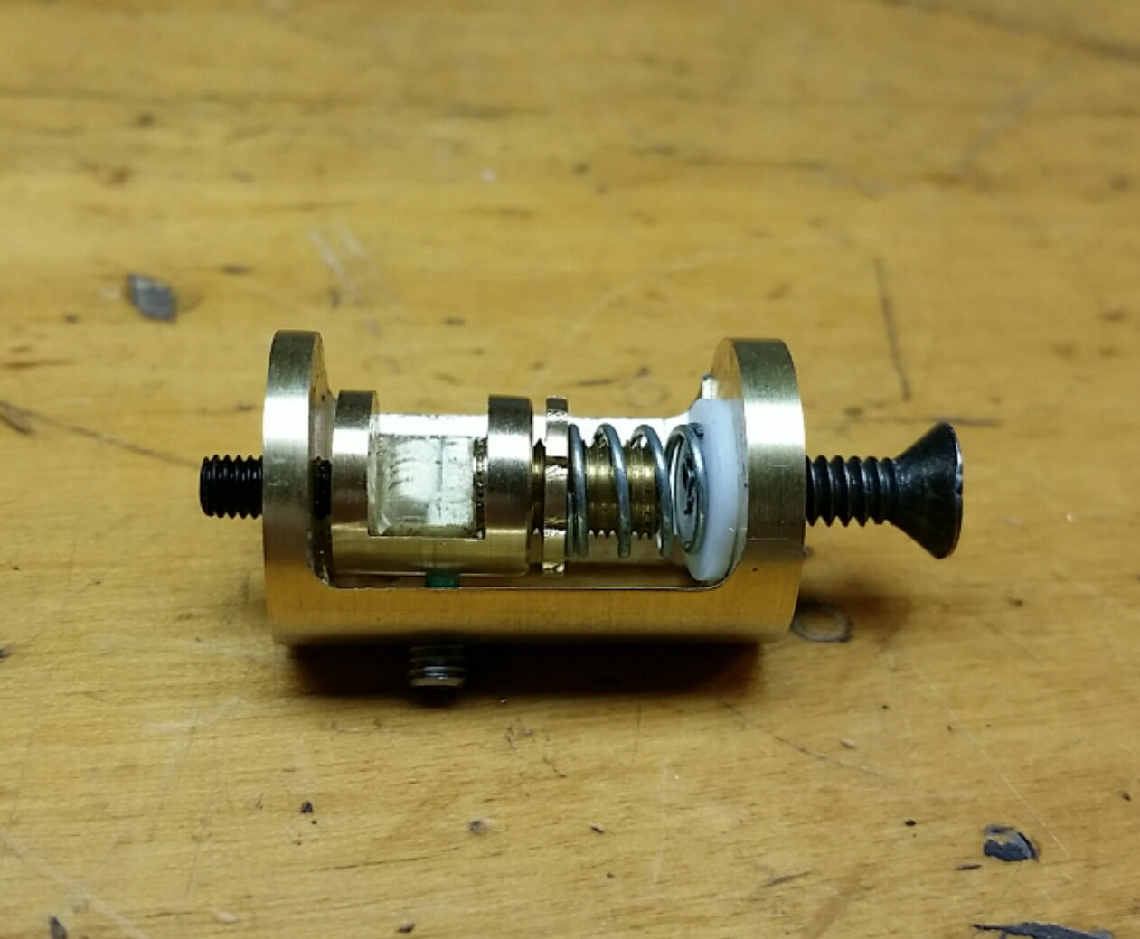
This bed mount concept involves a brass clamp with a large brass set screw (coming up through the bottom of the clamp) to secure to the corner (or side) of the bed. This large set screw also has a threaded nut on it (also brass) to dial in the spring tension and the bottom of the spring sits on a non-conductive spacer. The sides of the clamp are separated from the (you guessed it: brass!) mount itself by set screws with non-conductive tips so that they will also be electrically isolated. Then the height of the clamp is controlled by a single set screw (drawn as a standard M3 socket head screw above) that also serves as the only electrical connection between the interior clamp and exterior mount. The purpose being that, when wired (wires not shown), downward force on the bed greater than the force of the spring will compress the spring and break the electrical connection between the clamp and the top set screw, allowing it to act as a “normally closed” end stop switch.
The amount of machining involved in making this whole thing happen was the impetus I needed to finally wire up my TinyG and CNC converted Sherline lathe/mill and so began an epic saga of trying to figure out how the heck to do that. And then use that to make stuff. CNC machining is hard. Enough said on that point for now.
The first attempt actually looked pretty good, but looks can be deceiving. A miscalculation when writing the Gcode for the milling operations had left the side mounted set screws shifted by a full millimeter each. Not bad looking, but not at all likely to be functional.
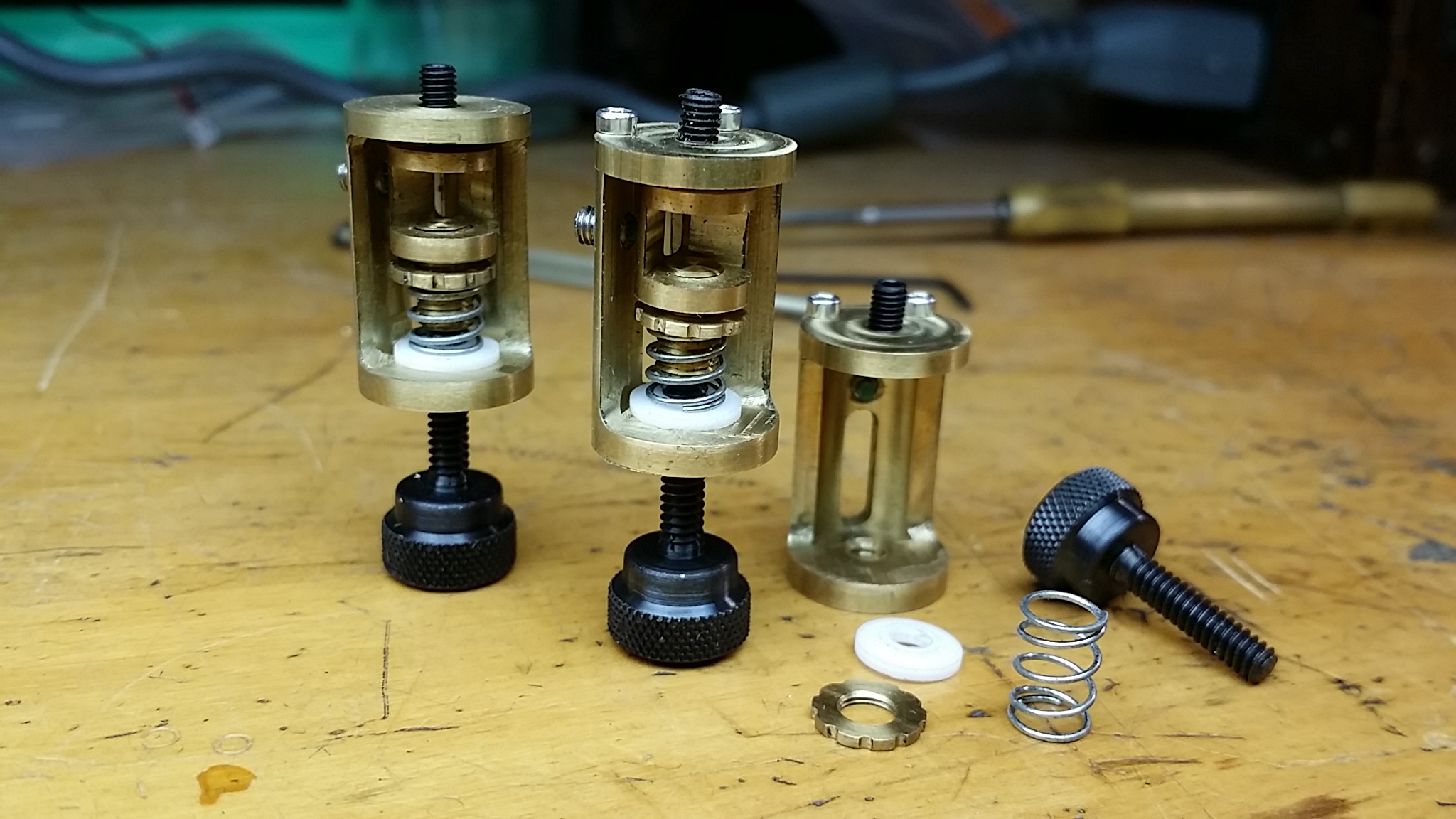
By the time I got the first one of these mounts more or less roughed out (the one on the left), I realized that the bed was going to be VERY difficult to install and remove unless I made all of the mounts with removable tops (my initial idea was that only the one side mount would have a removable top), but by then I was too lazy to completely remake the one with the fixed top.
Let me go ahead and critique this bizarre project for you to save you the time: This is highly impractical. The amount of machining and custom fabrication involved makes this in no way the kind of solution that is going to catch on and set the RepRap world on fire. Understood and agreed. It is however somewhat appropriate for a steampunk 3d printer I think and in keeping with my watchmaker sensibilities as well. Mechanical watchmaking is nothing if not impractical and I’m much more comfortable over-engineering a mechanical solution of absurd complexity than I am fiddling with inductive probes (no moving parts? what kind of sorcery is this?).
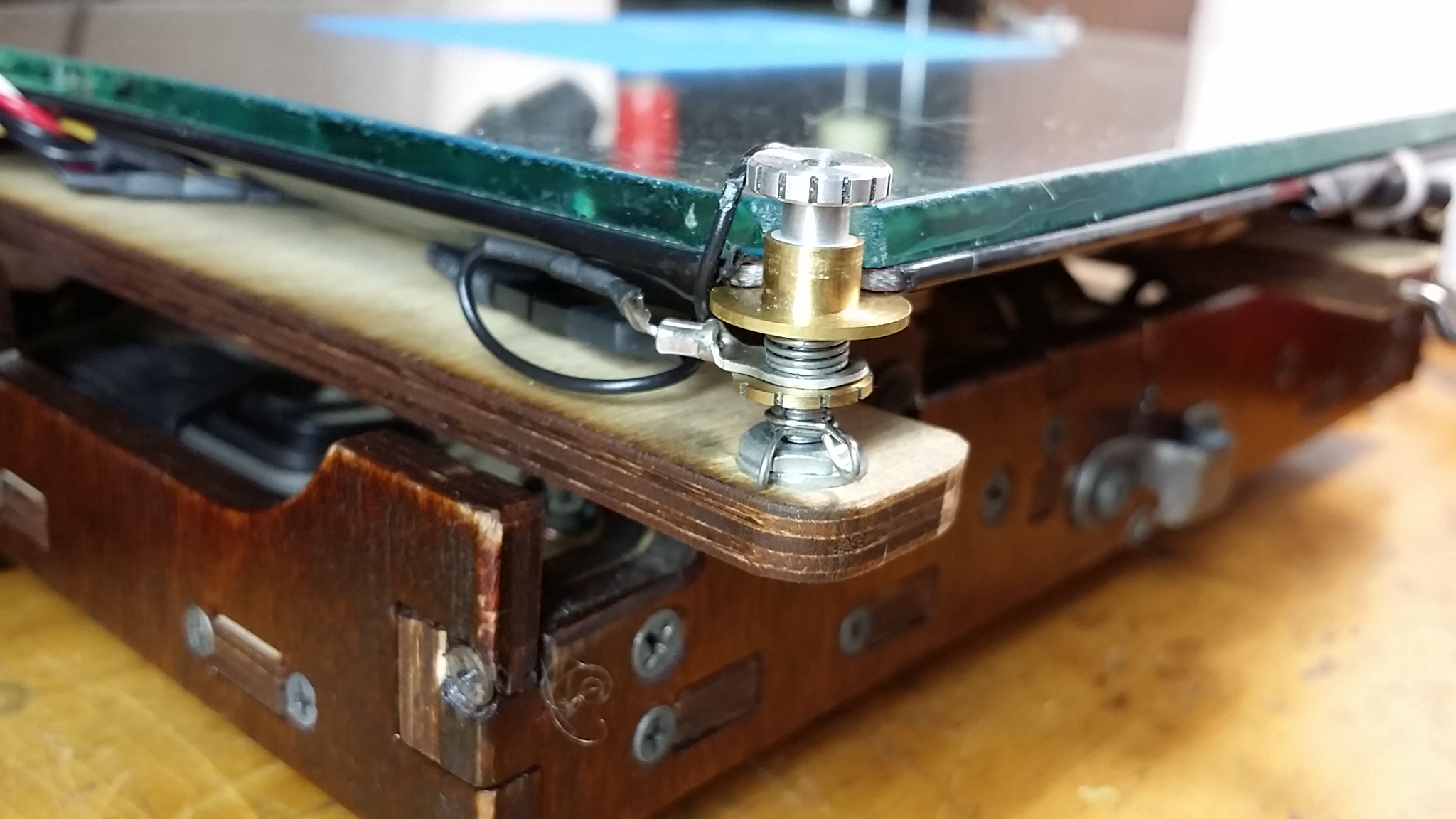
I finished the last of the machining on the evening before World MakerFaire NYC 2014 (well, on Saturday night, I was only going for Sunday) and began the install and waves of depression swept over me as I realized just how incredibly finicky the process of fitting and removing the bed would be amid fears that the things might not even work at all. Completing any project with so much personal time and effort invested always comes with a bit of sadness, but I’m happy to say my despondency lifted as I finally got the mounts attached to the carriage (who thought thumb screws were going to be accessible here?), got the bed installed (lord give me patience…) and got everything wired up. In fact I started to suspect it really was going to work.
I only did some very basic testing that night to confirm that the end stop functionality of each mount was working and put off actual testing until I could update my firmware and try to remember some of the Gcode for Marlin’s “automatic bed leveling” functions. Then finally, a few days later, it was time to run the darn thing.
I have to apologize that I didn’t wipe the fingerprints off the lens on the cell phone camera before filming the above, but you can’t run a first print twice, so it is what it is. And the good news is that they worked right out of the gate.
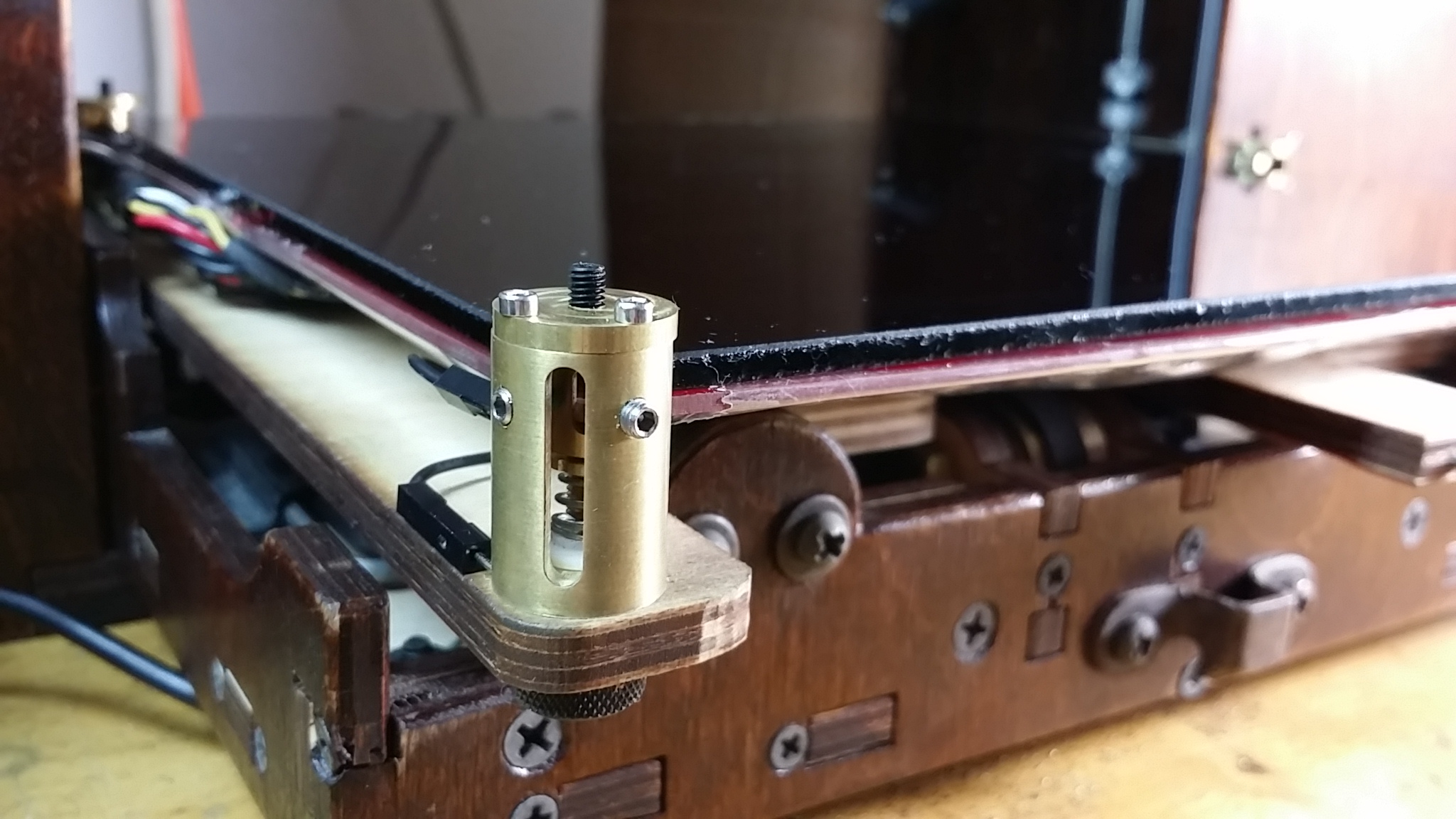
I had a minor malfunction a couple days later when one of the springs shifted enough to touch the tip of the screw attaching the mount to the carriage. This meant that the electrical circuit was always closed regardless of the compression of the spring and caused a decent nozzle crash or two before I could figure out what was happening. I’m happy to say that with a minor adjustment to the location of the mounts that has been resolved and the thing is printing happily and consistently as I type this.
Because of the SUPER-finicky nature of the bed installation/removal process (I knocked the nylon tips out of several set screws in the process), I may switch to a smaller glass plate with only the PCB heater held in the clamps. Then I can just use binder clips to hold the glass plate down (old-school RepRap style) and switch it out more easily (read: with any hope of success in under an hour). This would also address the other major practicality concern I have which is the weight of the glass bed on these very fine points of contact when I fold the thing up into its suitcase form. If I can easily take the heavy part of the bed off for travel I’ll feel a lot better about its chances of surviving a trip on the subway and printing successfully on the other end. I may also remake the entire carriage in machined aluminum to try to improve it’s rigidity, but that is an open question for another day.
Hello.
Sounds genius.
Just wondering how this react when in the following scenario:
a print is starting to warp, the nozzle hit the printed thing, the bed springs compensate the height difference, and layers after layers, the print should eventually finish well.
Yes, that can happen, assuming of course that the nozzle hitting the warped part of the print doesn’t knock the print off the bed.