I’ve been putting off this post thinking that I wanted to “perfect” my setup before making it more public, but I haven’t had all that much time to work on it lately and my vision for where I want to go with the hardware has escalated considerably (vaguely hinted at at the end of the post), so I decided to go ahead and write it up for now in the hopes of encouraging others to explore this route. It’s a very hot topic in the 3d printing world these days so hopefully my experiences with this particular method can serve as inspiration to someone else.
For anyone reading who has never used a Fused Deposition Modeling / Fused Filament Fabrication (FDM and FFF are just two general terms (the former trademarked by Statasys) for additive fabbers that use plastic filament as the feedstock) 3d printer or perhaps is just new to the hobby/art/science/craft, it’s important to understand that your first layer is your whole world.
If the first layer lays down nicely, with the right layer height across the whole part, proper bed adhesion (the various techniques applied to get the plastic to stick to the bed could fill several books already), etc., the rest of the part has a fighting chance of turning out OK. If the first layer has issues, your chances of success for the rest of the part drop off dramatically (somewhere in the range of slim-to-none). Everyone that’s ever spent much time with an FDM/FFF 3d printer has almost surely spent countless hours adjusting the height of the bed at the various corners (only three if your lucky – Gods help you if you have four adjustment points), dialing in their Z end stop height and correcting for changes by entering Z offset variables into your slicer or into the starting G code (Cura, a great open source slicer otherwise, bizarrely, does not allow for Z offset).
If you have an incredibly rigid bot and/or a very environmentally stable workshop environment you may only have to do this once in awhile, especially if you mostly print with the same type of filament and don’t switch nozzles or hot ends. But if you happen to have a bot made out of plywood (me), print with the window open all the time (me), like to switch between different nozzle diameters for different models (me), have nozzles dedicated for different materials (me) and even switch hot ends between 1.75 and 3.00 mm filament from time to time (me), you can very easily spend more time fiddling with the above mentioned height adjustment posts and Z height parameters than doing anything else IN THE ENTIRE REST OF YOUR LIFE (like designing and fabbing stuff). Because of this, I am perhaps more keenly aware of the benefits of a lazy-man’s way of solving this problem than most, and recently set out on a quest to figure something the heck out.
Bed leveling is the term that has all but irrevocably taken hold among 3d printing enthusiasts for something that is more properly referred to as tram adjustment or correction/compensation (as seems more apt if one is applying a software fix to the problem). I’ll have to assure Whosa whatsis that I am not stalking him based on the number of time he pops up in this post (the guy is pretty bright), but it was after reading a post or comment of his that I came to realize the incorrectness of the term “bed leveling” and started using tram correction instead.
For one thing, it doesn’t matter if the bed or any other part of the printer is level. What matters is that the axes are square to each other, and in the parlance of milling and presumably other machining crafts, the state of the axes being square to each other is referred to as being “in tram” and the act of getting to that state is referred to as “tramming”. Given the similarities between 3d printers and milling machines, there’s no good reason (except perhaps the inertia of language freshly, but firmly seeded) not to use the same terms to describe the same states and operations for 3d printers. In addition to there being no need to reinvent the wheel, do we really want to sound silly or non-nonsensical when we talk with our old-school, subtractive machining brethren?
Secondly, even if we were to concede that “bed leveling” were an appropriate term to describe the act of adjusting the bed to put the build plate in tram with the rest of the machine, what most folks mean when they refer to automatic bed leveling is actually the process of probing the bed to allow the firmware to internalize some correction parameters for the Z height at multiple points on the X-Y plane. Effectively the firmware models whatever misalignment (un-squareness, out-of-tram-ness) is present as a plane of some (now known and well defined) tilted-ness and then corrects for this in the G code commands which drive the various motors.
If you can at least find some reason in the above points, you can hopefully appreciate why I’ve come to refer to this functionality as automatic tram correction rather than “bed leveling”. The fact of it being automatic merely means that the bed mapping doesn’t require direct input from the user other than perhaps to initiate the probing routine. Automatic tram correction of this sort is becoming increasingly common in the FDM/FFF 3d printing world, and thank the lords for it, because in my experience at least, it can save one a lot of time, aggravation and mis-spent plastic.
The most commonly employed RepRap automatic tram correction solution prior to this point has been to mount a mechanical probe on a servo to rotate into position during the probing routine and then swivel back up out of the way so as not to interfere with the deposition of plastic. Getting good reliable performance out of the servo turns out to be something of a headache for most folks however, and it just generally has lots of moving bits.
(Skip to the 1:00 mark to see the servo in action.)
The UP! Plus 2 (and presumably some others?) relies on a removable probe that one installs specifically for the probing routine and then removes when done. It reportedly works very well, but it does lack a certain elegance one must admit.
(Likewise, skip to the 1:00 mark to see the probe installation.)
Folks in the deltabot world have made tremendous strides recently using Force Sensing Resistors (FSRs) underneath the build plate. The genius of this approach is that there are no moving parts. You just wire the FSRs to be read as your Z end stop and then when you run the probing routine the nozzle gently tapping on the build plate tells the bot how high the bed is at the various probing points. The downside is that the FSRs only work reliably to about 70°C, making them not well suited to a heated build platform without heat shielding the sensors in some way.
(Deltas do a lot of probing since they are not only correcting for the tram of the bed, but also calculating some kind of whacky parabolic correction related to the three arms working in concert.)
A good friend with a deltabot struggled also with a tendency of the build plate to settle in and trip the sensors in an unpredictable fashion (if I understood him correctly) and resorted to just attaching the FSR to the tip of the (cold) nozzle to perform the probing routine. One advantage of deltabots that he likes to remind me of is that the most stable bed is one that doesn’t move, so he doesn’t have to perform the tram correction probing routine very often.
Another interesting approach to automatic tram correction is documented here. Thankfully the linked Thingiverse page is not in Russian so I could actually understand how it works.
(You must learn to think, in Russian…)
Printbot has recently introduced automatic tram correction as a standard feature in their Metal Simple. They way Brook and his team have done so is to employ an inductive probe next to the nozzle that can read a metal print bed from several millimeters away. The enormous advantage of this approach is that it doesn’t employ any moving bits and the probe can remain in place permanently.
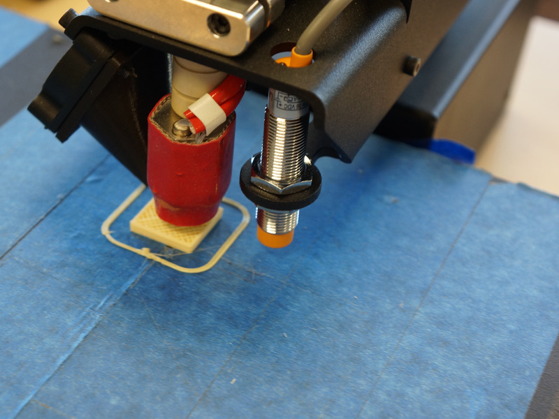
The downside of the Printrbot solution from my perspective is that it necessitates a metal build plate. I’m not opposed to a metal build plate necessarily, I just didn’t like the idea of committing to one for perpetuity, especially when I’ve become so accustomed to using glass and still want to install a properly flat Garolite build plate for printing with Nylon at some point, neither of which would work with an inductive probe.
During one of my searches on the subject when I was trying to find information about high temperature FSRs, I stumbled upon a comment by Whosa Whatsis buried deep in that Google Groups thread about using FSRs on delta style printers. His suggestion was just to use the spring loaded bed height adjustment mechanism that is common on many RepRap style printers as an electrical connection and wire that as an “always on” end stop.
If you were to do that for each of the mounting points for the build platform, you could just use the nozzle as the probe and each time it depressed the bed on the springs it would break the connection and serve as the Z end stop.
Although this seemed like an obvious stroke of genius to me, it got literally zero traction in that thread and, despite searching around and reaching out to Whosa whatsis on Google+ to ask if anyone had tried such a thing, I have yet to find any evidence of someone else giving it a go, so I decided to be that guy.
The first thing to do was to convert my bed from four points of adjustment to three. I’ve known for a very long time that doing such a thing would be a good idea, but for some reason had resisted doing so. It was a huge relief to have it finally done however because, as anyone who has tried both can tell you, tramming a bed with four points of adjustment is orders of magnitude more difficult and time consuming than doing so with only three. If you’ve ever worked in a restaurant with tables with four legs, you surely know that it is impossible to keep all four feet firmly planted on the floor at all times. Three legs? Golden.
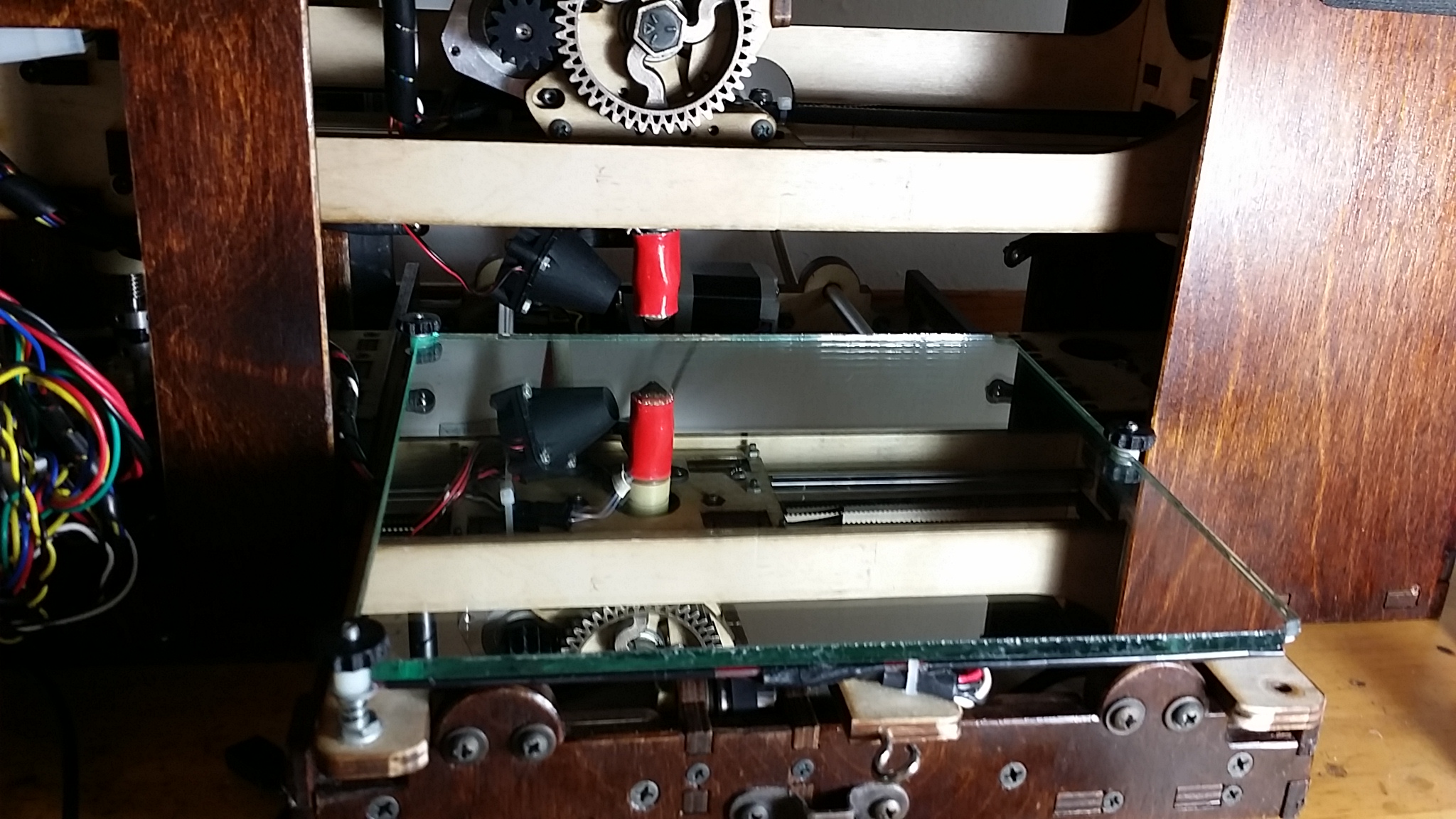
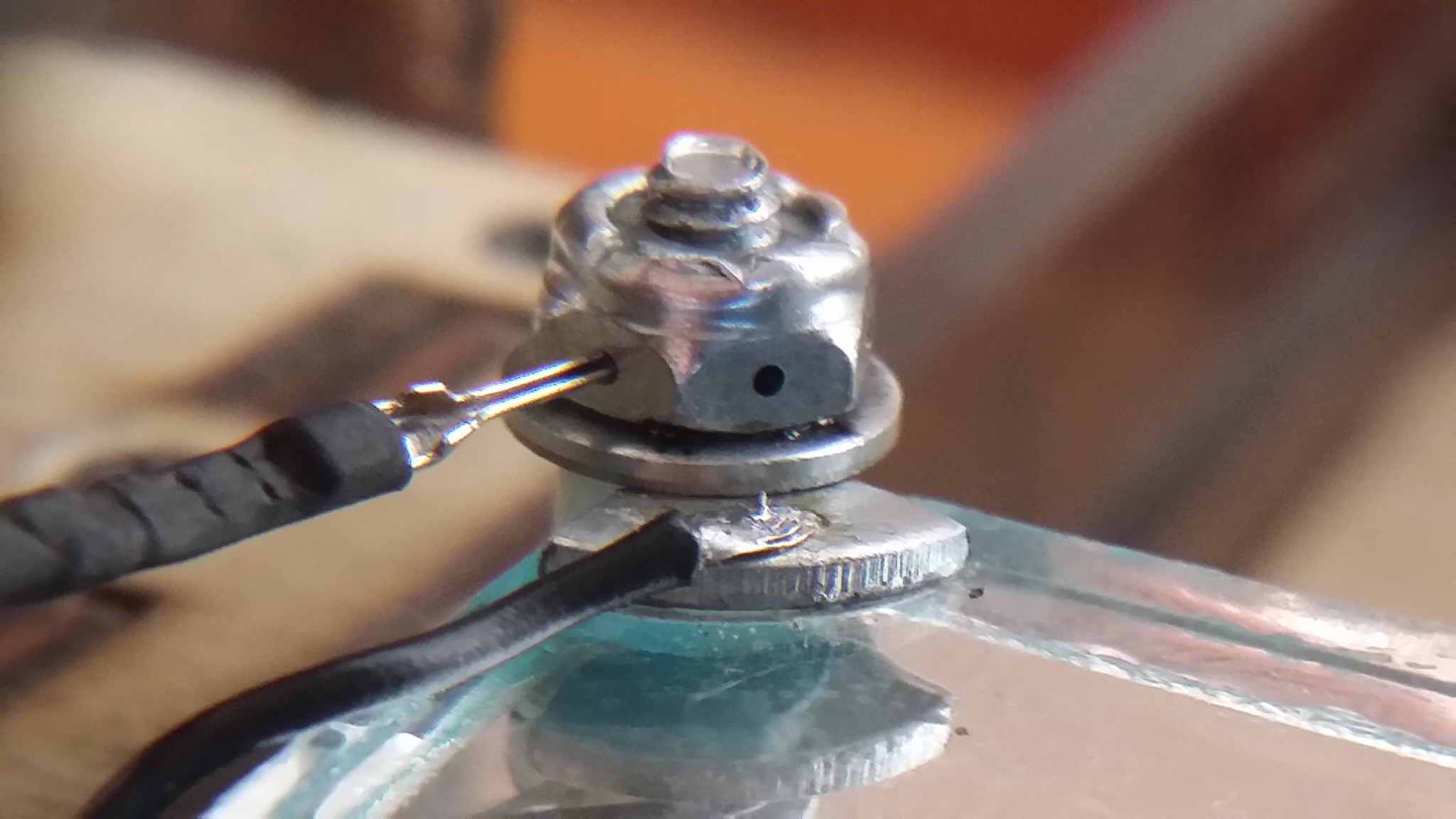
Since I knew the method I was attempting to develop/implement was completely experimental, I decided not to waste a lot of time trying to make it look nice, so the next step was to JB Weld a partial washer to each corner of the glass bed, weld washers to the bottom of some nylock nuts to serve as the upper contact point and then wire them both up.
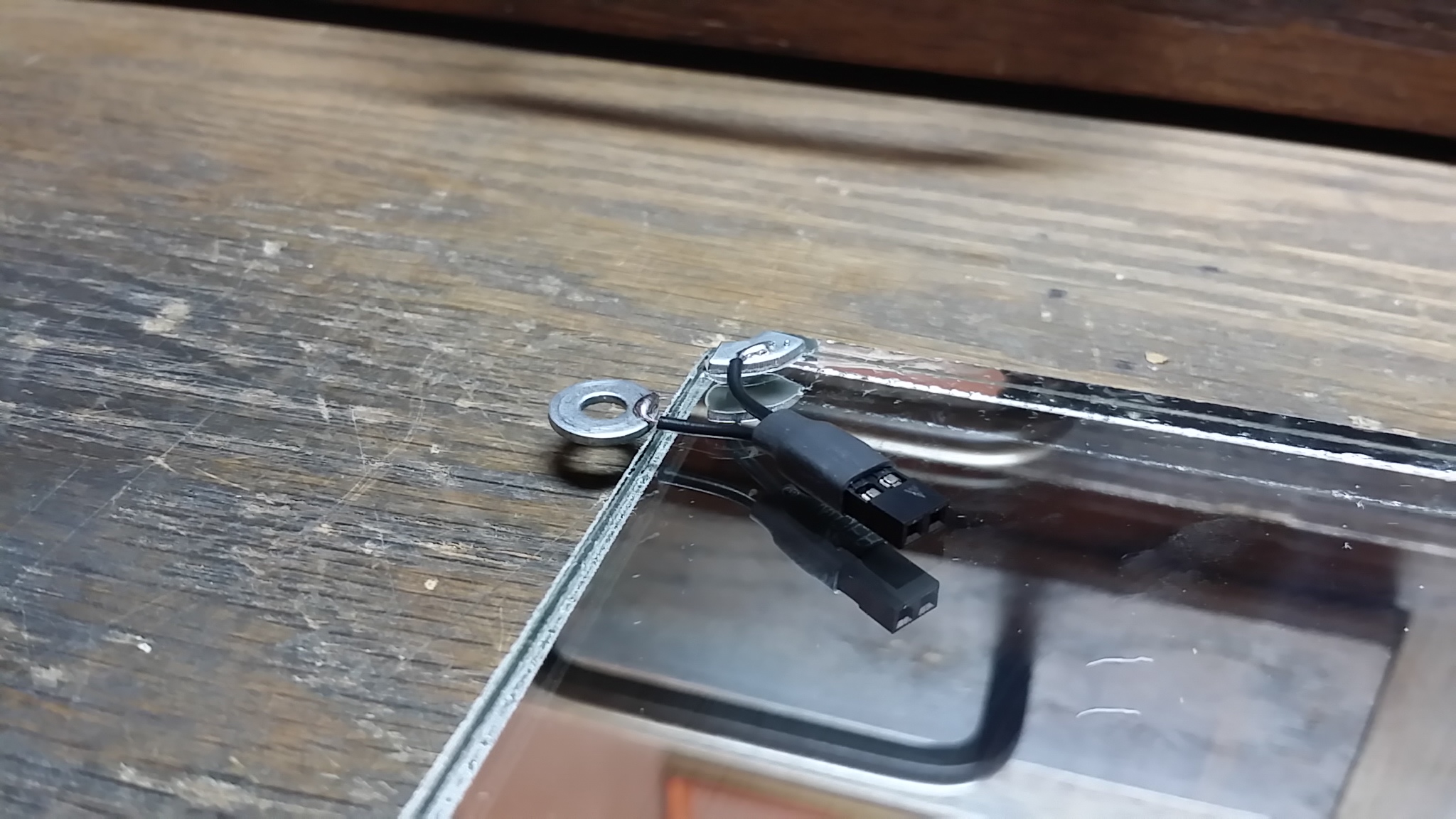
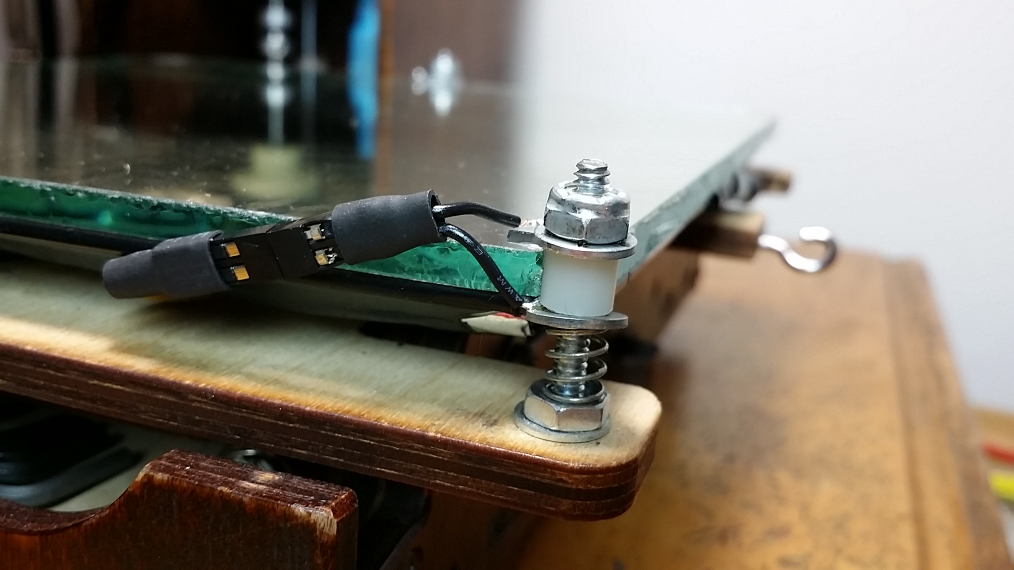
For this first iteration I used a second washer underneath the bed to carry the current through the threaded post to the nylock-nut/washer combo on the top. I wired such a contraption for each of the three support points and tested to see if they would indeed work as an end stop even, much less with enough consistency and repeatability to provide reliable tram correction.
While they did essentially function as end stops, there was way too much friction in the design, causing the whole carriage to flex substantially before triggering the end stop. More critically, the amount of flex was not at all consistent and certainly couldn’t be corrected for by just adjusting the spring tension. Despite these obvious shortcomings, I couldn’t resist trying to install some of the “bed leveling” firmware variations that Printrbot has floating around and giving it a shot. This proved just shy of completely disastrous.
It is worth noting that it may have been late at night when this first attempt was made and I may have had an adult beverage before hand. Kids, don’t try that at home.
When I loaded the firmware and tried to run the G29 bed probing routine (after much futzing with the nylock nuts and spring tension just to get the end stops to remain closed) I saw some wisps of smoke emanate from the general vicinity of the height adjustment posts and when they were triggered by the probing action I actually saw some sparks.
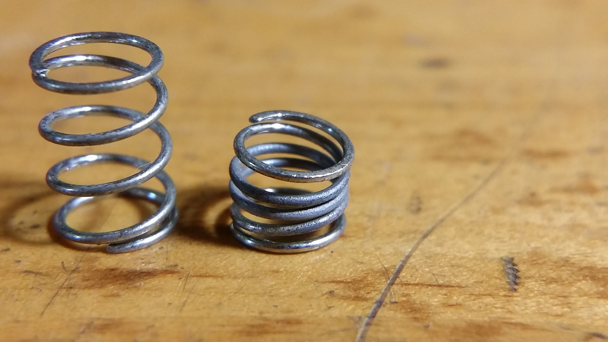
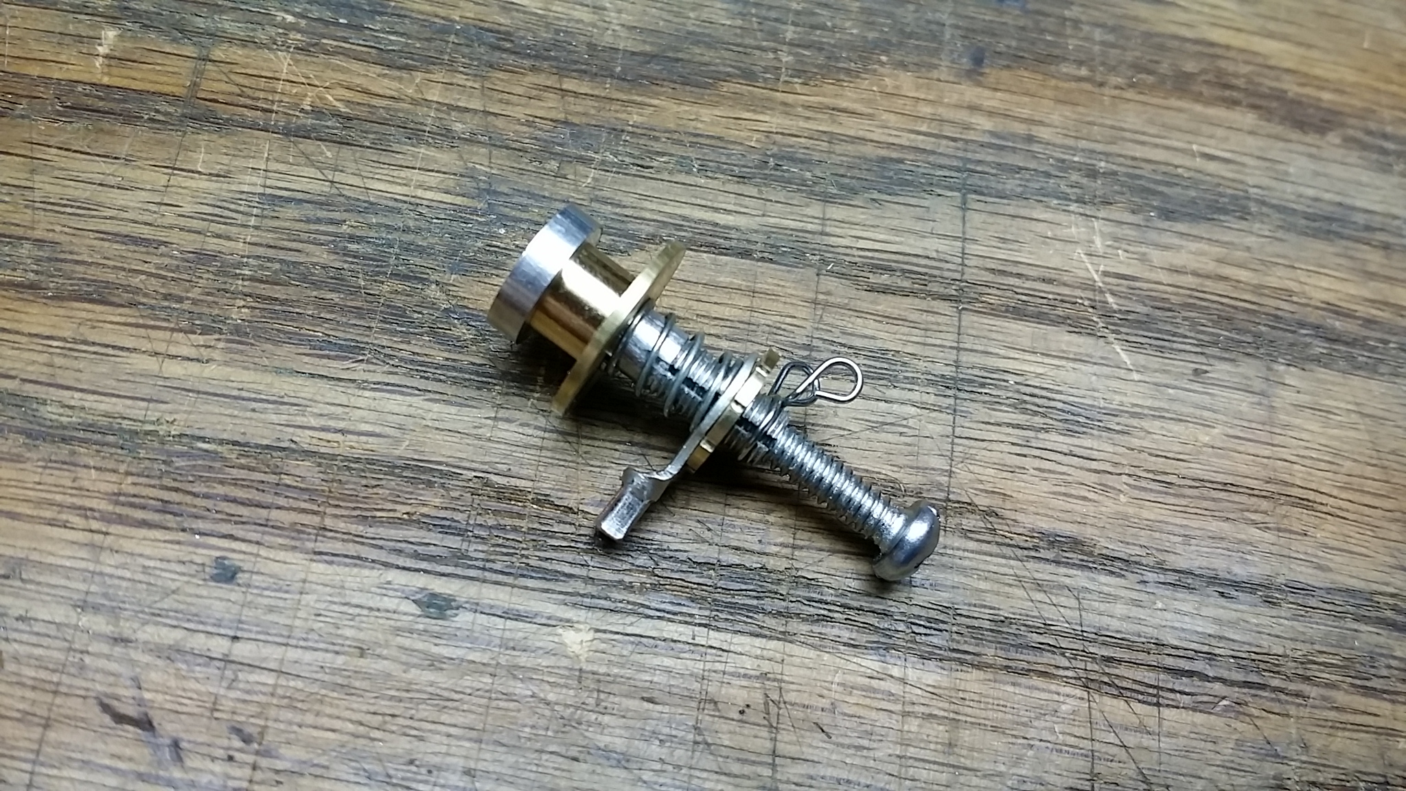
It was only after several days of head scratching, asking around about the potential power supplied by the end stop connectors and poking around at the connections that I realized that in my efforts to modify the heated bed to accommodate the third, middle-mounted height adjusting post I had exposed some of the electrical circuitry for the bed, which was likely shorting with the end stops in some horribly unintended fashion. It may also have been related to my disabling the Z end stop pullup resistors in the firmware at some point when I was trying to get things working. Kids, use me only as an example of how NOT to proceed. The above permanently deformed spring is apparently what happens when you send something on the order of 17 Amps through it all at once.
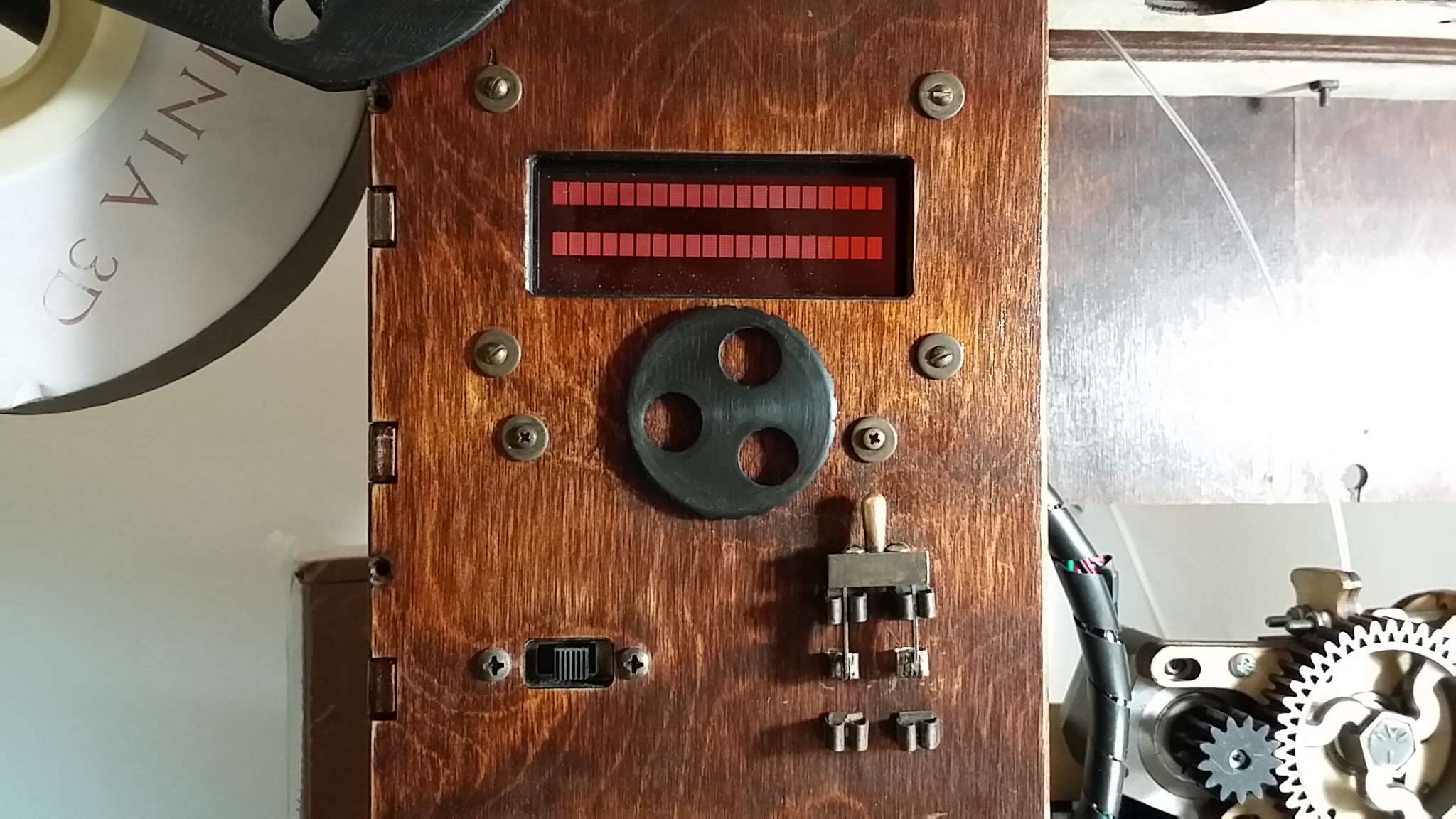
Some combination of these electrical follies and my frequent flashes and reflashes of increasingly questionable firmware resulted in a complete shut down of my Printrbot. I couldn’t get the thing to boot or talk to the computer at all and the poor LCD screen was just white stripes.
I became convinced I had fried my printrboard and Brook even graciously offered to send me a replacement (he gets some perverse pleasure from seeing me do unnatural things to my GO!) before I turned everything off and back on and reflashed the firmware successfully and told him the generously extended replacement would not be necessary.
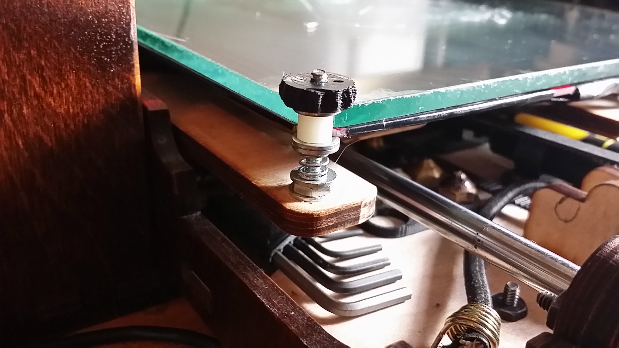
Ever undeterred, I set about iteration number two of the height adjustment end stop experiment with some nylon sleeves in between all the sliding bits and a quick plug/unplug connection for the nylock nuts themselves to facilitate rapid assembly and disassembly.
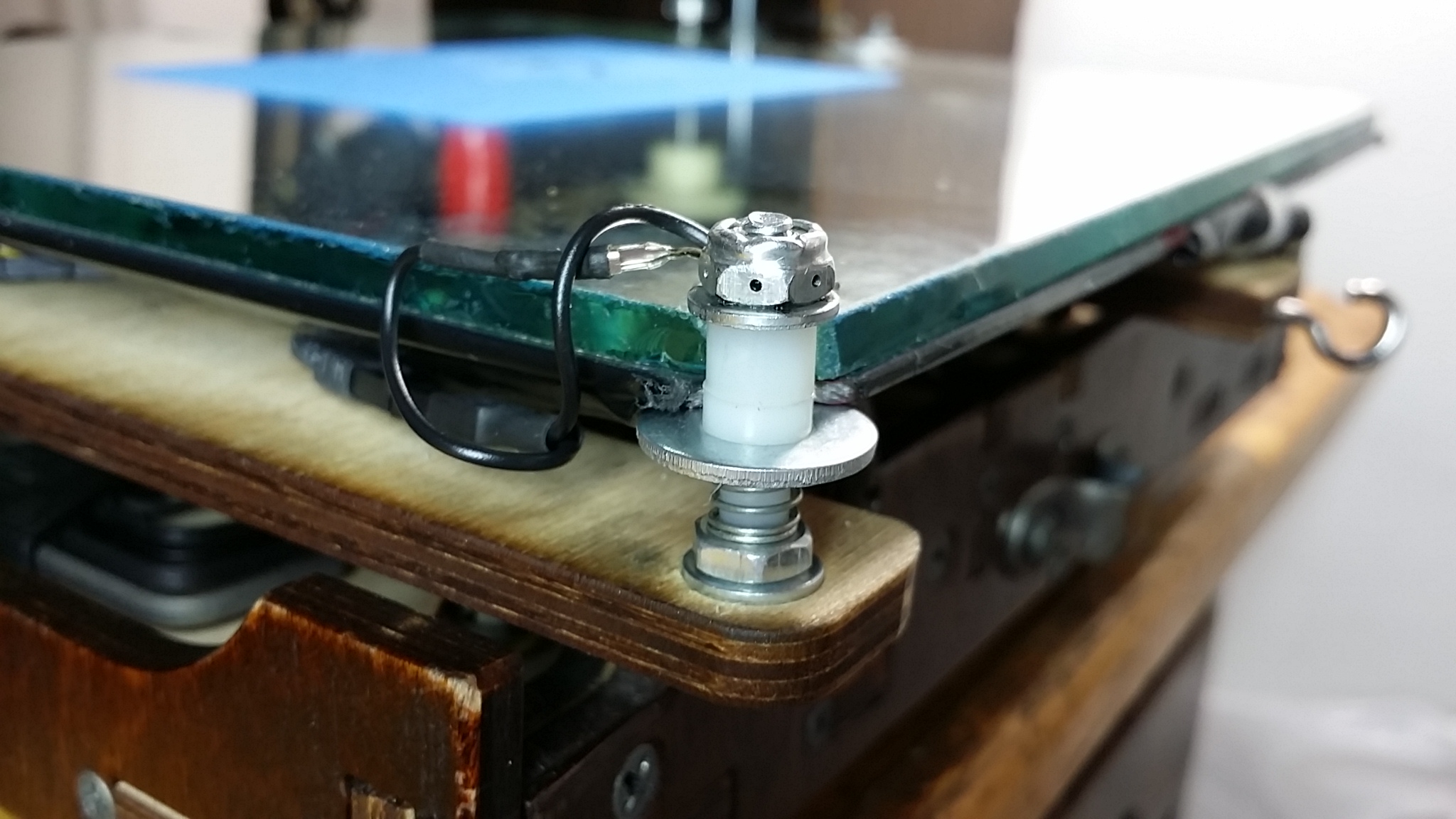
I found that the spring tension adjustment was quite critical for repeatability and reproducibility (word to you quality mavens), so I drilled a hole for the wire connector in each of the six sides of each nut so I could dial them in with some precision and, after dialing them in with some precision, darned if the thing didn’t kinda work.
Actually I’m underselling it here. It worked better than I possibly could’ve hoped given the motley assemblage of parts. The dialing in process mentioned above involved homing the Z axis while the nozzle was in proximity to one of the height adjustment posts and then measuring how far off it really was (after homing) and then rotating the nylock nut to increase or decrease the offset to try to match the offset measured in proximity to the other posts. I found that my middle-point post was the most finnicky and hard to adjust, so I set it to a comfortable mid-point in its range (it turned out to be right around -0.7 mm) and then proceeded to adjust the others to match.
After doing that, I started a test print (with a G29 bed probing routine in the start code) while entering a different M212 (probe offset) height to match what I was observing for the first layer height until I got it printing a nice first layer each time. Now granted, I wasn’t shooting for sub-100 micron layers (I usually print in the 120 to 240 micron range), so I can’t say how deadly repeatable it really was/is, but I completed a bunch of prints with the bed probing routine in the start code including changing nozzles and changing hot ends without touching the height adjustment nuts or the probe offset and each one came out at least as good as what I’d come to expect after extensive fiddling with the tramming previously.
It was at this point that I decided the concept had been proven and I was ready to craft a proper end-stop-wired-adjustable-height-adjustable-spring-tension-bed-support-post. That is a story for another day however.
Any update on this? What’s the latest greatest iteration look like ?
The latest/current version is found in this post:
http://ei8htohms.tinyparts.net/?p=1111
And they work great!
Hi,
I am watching your effort with interest as I am using the “Russian” system for my bed leveling on my Hugo/Printerbot. I have redesigned the nut holder to my machine. I considered setting a switch to the table but as I think that having adjustment available redundant I opted for the switch on the Z screws and direct mounting of the table to the bed.
Regards,
Reece
Sounds great! Do you have any pictures of your set up? Do you find that you need contact switches on both sides (at each lead screw), or can you get consistent triggering with just one?