So after my last round of functional but peripheral upgrades (getting all the tools into handy locations) I decided it was time to focus some time and effort on the printing performance of the bot (an idea that felt almost novel after all of the aesthetic mods I’d otherwise been consumed by recently).
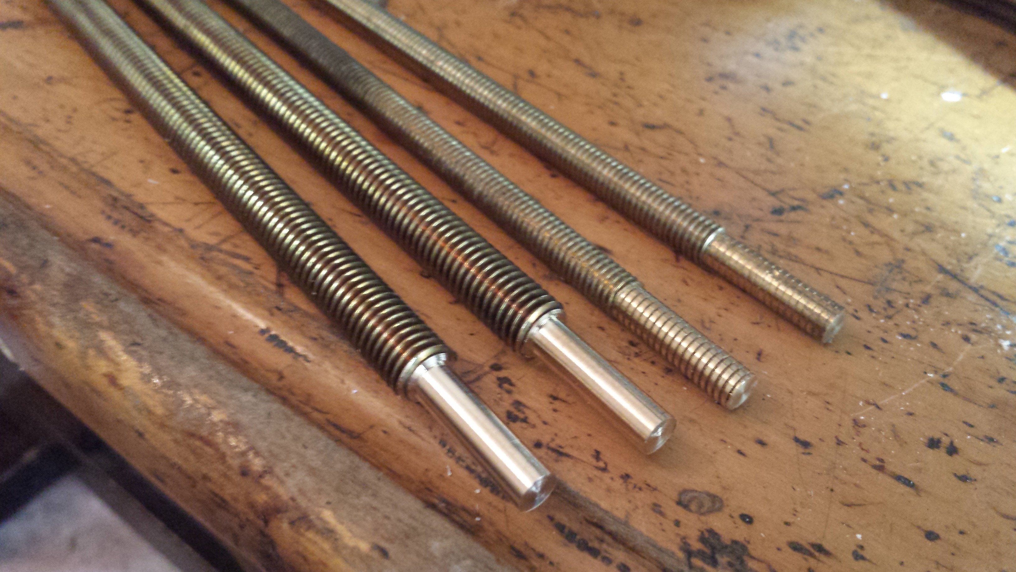
It was clear to me that the motion in the Z direction could use some refinement because the x-axis carriage seemed to wobble back and forth a little bit when raising or lowering the extruder manually. I wasn’t sure if the six millimeter brass threaded rods just had inconsistent threads, if the threads were getting worn (possibly because the nut adapter I’d made for the stainless nuts to fit into the traps for the original 5/16″ nuts were pretty crude and likely not as perfectly aligned as one would wish), if the slight bend in the rods from when new was to blame (poorly packed when shipped from the distributor) or maybe if the rods were just too thin, but all of these things could be addressed by just changing them out, so I decided to go for eight mm brass rods instead.
I machined down both ends to fit the PTFE bushings I’d made for where the rod connects to the top of the bot and also the brass couplers that I’d been using previously, but before I tried to reinstall them, I decided I might as well change out my drive belts for the X and Y axis at the same time to some GT2 belts and pulleys I’d purchased previously and just hadn’t gotten around to installing. I didn’t think the printing performance of my bot was nearly good enough in other regards to make this upgrade noticeable yet, but I also didn’t figure it would hurt and since I already had the thing partially disassembled, I might as well upgrade while it was most convenient to do so.
When installing the new threaded rods, I kept trying to test them to insure they were properly free and well aligned before reassembling the top of the box and kept finding the carriage to bind and cause the motors to slip and skip and grunt and generally not cooperate when trying to move it up and down manually (driven by Repetier at various speeds).
I tried a number of adjustments and tweaks before deciding to try out the original printrbot Z couplers (that I’d never used up to that point) thinking that they might give the rod coupling more flex and better centering (more on that in a moment) than the brass couplers I’d made and had been using up to that point. When even that didn’t work, I finally wised up to the fact that maybe the top of the box being installed keeps the smooth and threaded rods properly aligned and that this alignment is critical to keeping the carriage from binding and sure enough, that did it.
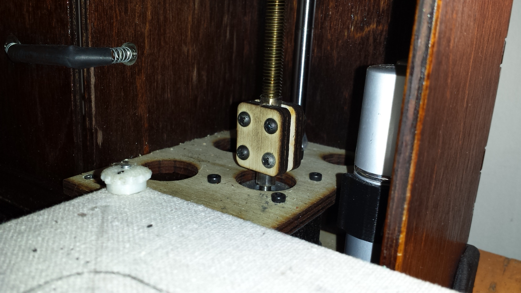
The problem I was finding with the brass couplers I’d made was that I had added plastic tubing to the connection to give them a little more flex than the metal on metal connection would otherwise have and when I tightened down the set screws the plastic tubing allowed the motor shafts and/or brass rods to push off to one side and tilt a little. I plan to modify the couplers by adding two more set screws for each rod and motor shaft at some point, but the laser cut couplers from printrbot are working great, so I’m not in any hurry. The only downside to the printrbot couplers really is that the one on the left side rather wants to grab at any stray wires that might be nearby and there are a lot of stray wires inside the tight confines of the box.
Oh, and by the way, the new threaded rods have at least as much wobble as the old ones, so I’ll be looking into some proper trapezoidal threaded rods in the near future. Progress ain’t free.
When installing the GT2 belts for the Y axis, I struggled somewhat finding the right amount of tension, a problem greatly exacerbated by the simple wood clamps holding the ends of the belt in place and the sub-optimal access provided by the door in the bottom of the drawer.

I futzed with the belt tension until I got it good enough to do some printing with at least and decided my next project would have to be a proper tensioner.
Inspired by some simple belt tensioners on Thingiverse with a toothed slot to slide the belt into, I decided to build on this idea by making the toothed slot inside a small wedge so that the tension of the belt itself would squeeze the slot around the belt. After several design iterations with OpenSCAD and various printed prototypes, I settled on this design.
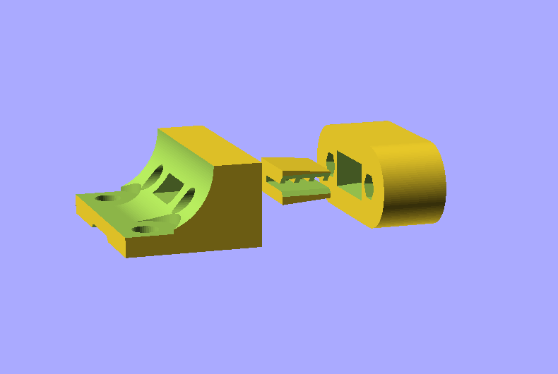
The mounted portion has two trapped nuts for M3 hex bolts and also has a toothed channel on the bottom to clamp down the other side of the belt. This allows these three components to replace both of the clamps from the original design.
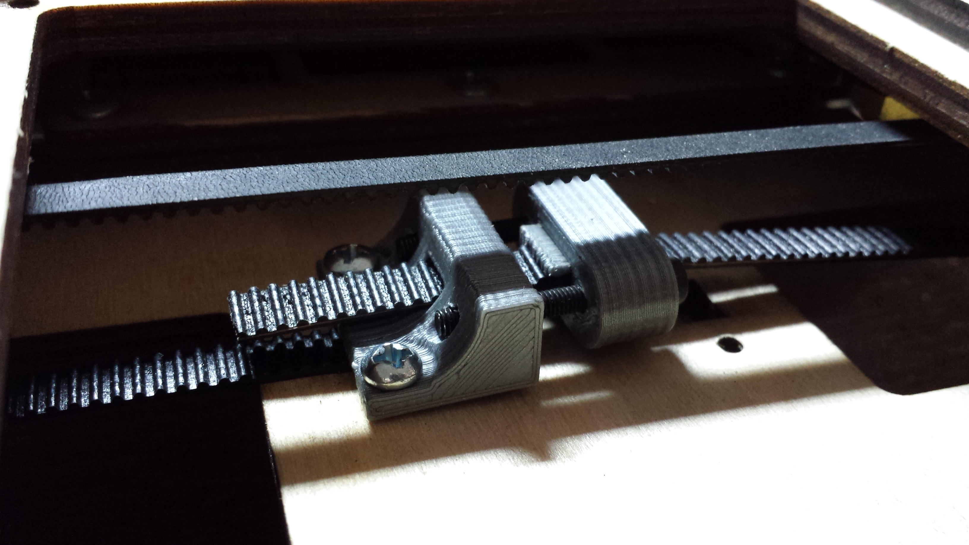
I’m really quite proud of the finished product’s performance and looks and dutifully uploaded a customizable version to Thingiverse that can accommodate either GT2 belts or the original printrbot belts and can be modified in various other ways as well. My only complaint with the design is that the tensioner holds the belt a little farther from the underside of the carriage than I would prefer, something that surely introduces a small error in the consistency of the travel. Motion in the Y direction basically being slightly exaggerated the closer the tensioner gets to the idler since the belt is not perfectly in line with the top of the idler. This is surely a very small error so I’m not obsessing over it. Yet.
Initially I installed the belt with a half twist between the pulley and the idler so that the smooth back of the belt would ride on the smooth idler bearing and theoretically smooth out the power transmission to some small degree. This is a subtle mod introduced by nophead some time ago that hasn’t found widespread adoption but sounds sensible enough and is very easy to implement. For my situation I found the twist caused the belt to run a little too close to some of the wiring in the bottom of the drawer however, so I flipped the belt back to the more “normal” orientation after just a few test prints. I did leave the belt for the X axis half twisted for now, but I can’t say if it makes any difference. I may consider it again when I get around to making a tensioner for that belt also.
The next big challenge I wanted to tackle was how to install a fan for active cooling. I’d been frustrated in the past when trying to print small objects in PLA and found that only by printing at very slow speeds was I able to allow the material to cool sufficiently to keep from deranging things when successive layers of plastic were extruded onto still molten material. The tried and tested solution to this problem is to add active cooling (a fan blowing on the tip of the nozzle as it lays down the material), something that most FDM home printers come with by default these days (all printrbots now come with cooling fans installed).
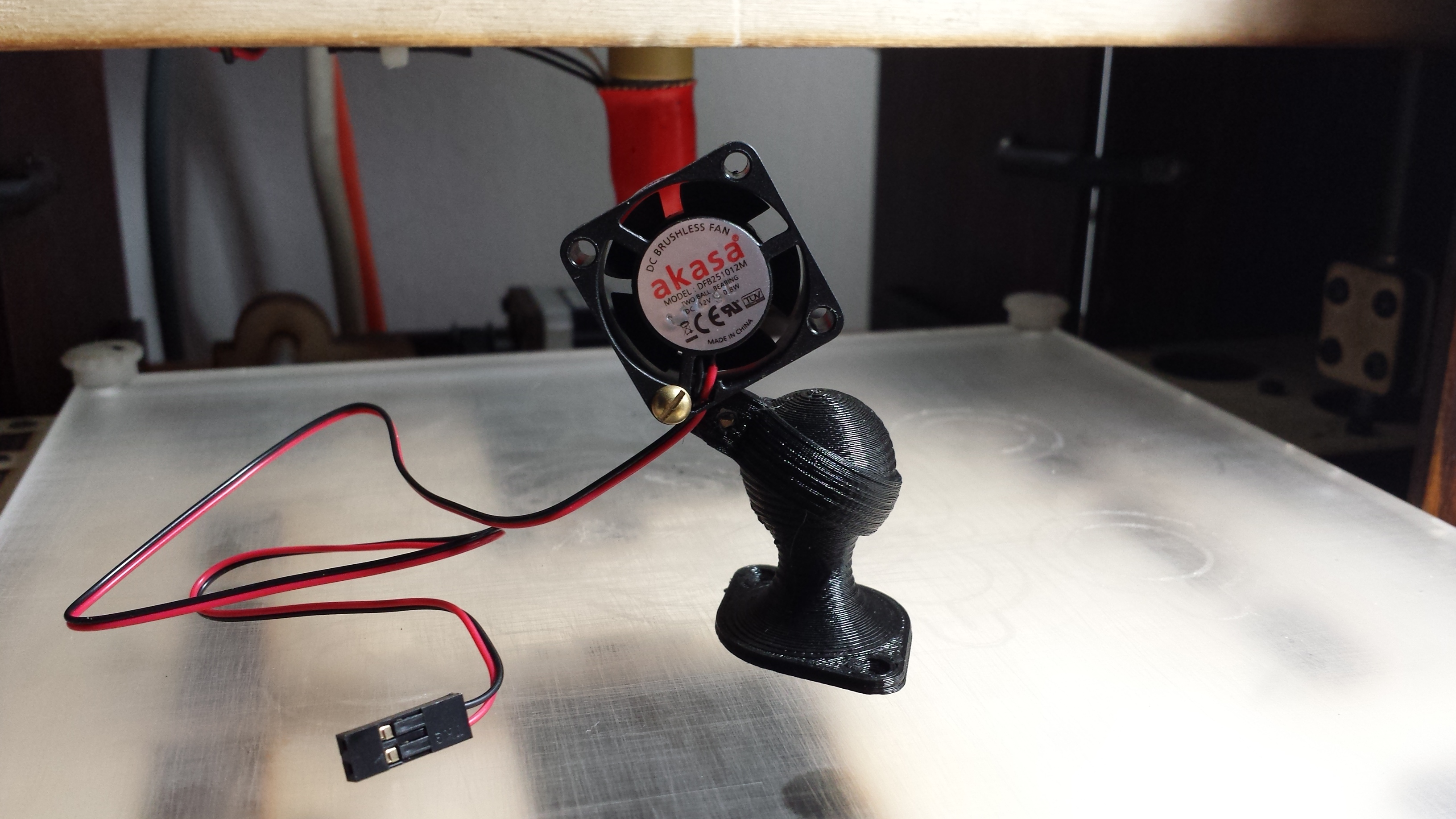
The challenge for the GO is that there is not a lot of room to mount a fan that won’t get in the way of folding the thing up for travel. I decided the only viable option was to fit a fan that was small enough to attach directly to the underside of the X axis carriage and be mostly tucked behind the extruder. This would dictate a pretty small fan, so I ordered a tiny 25 millimeter job and eventually got up the gumption to start sketching out mounting ideas.
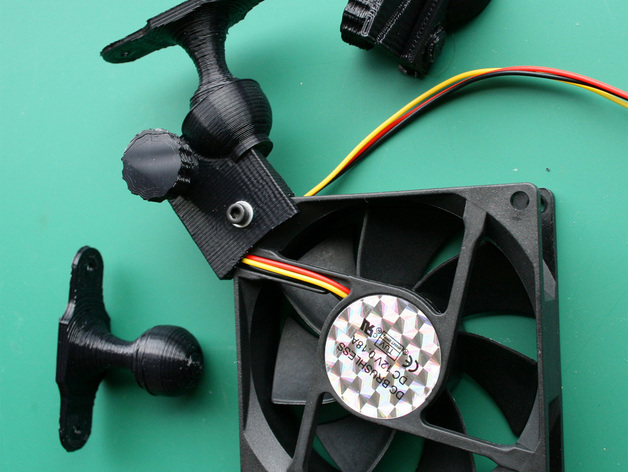
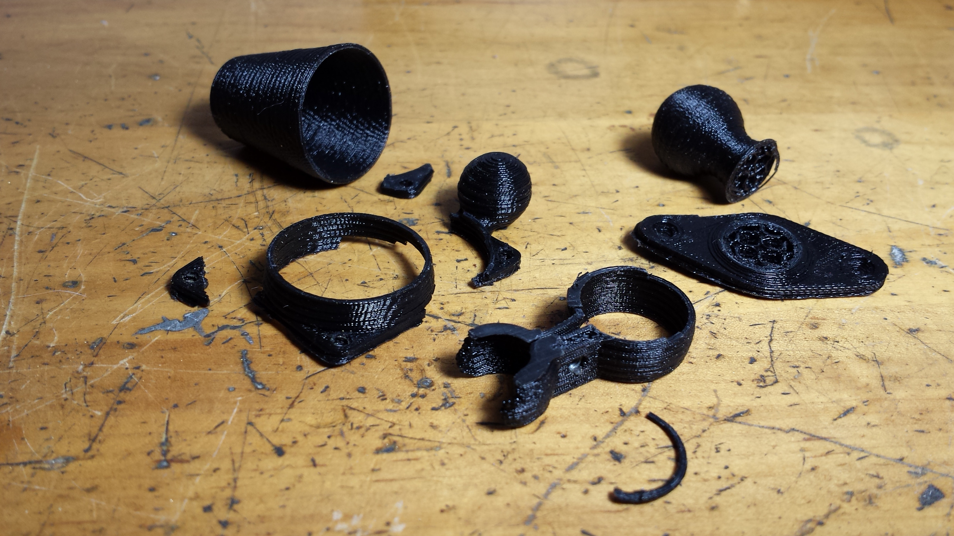
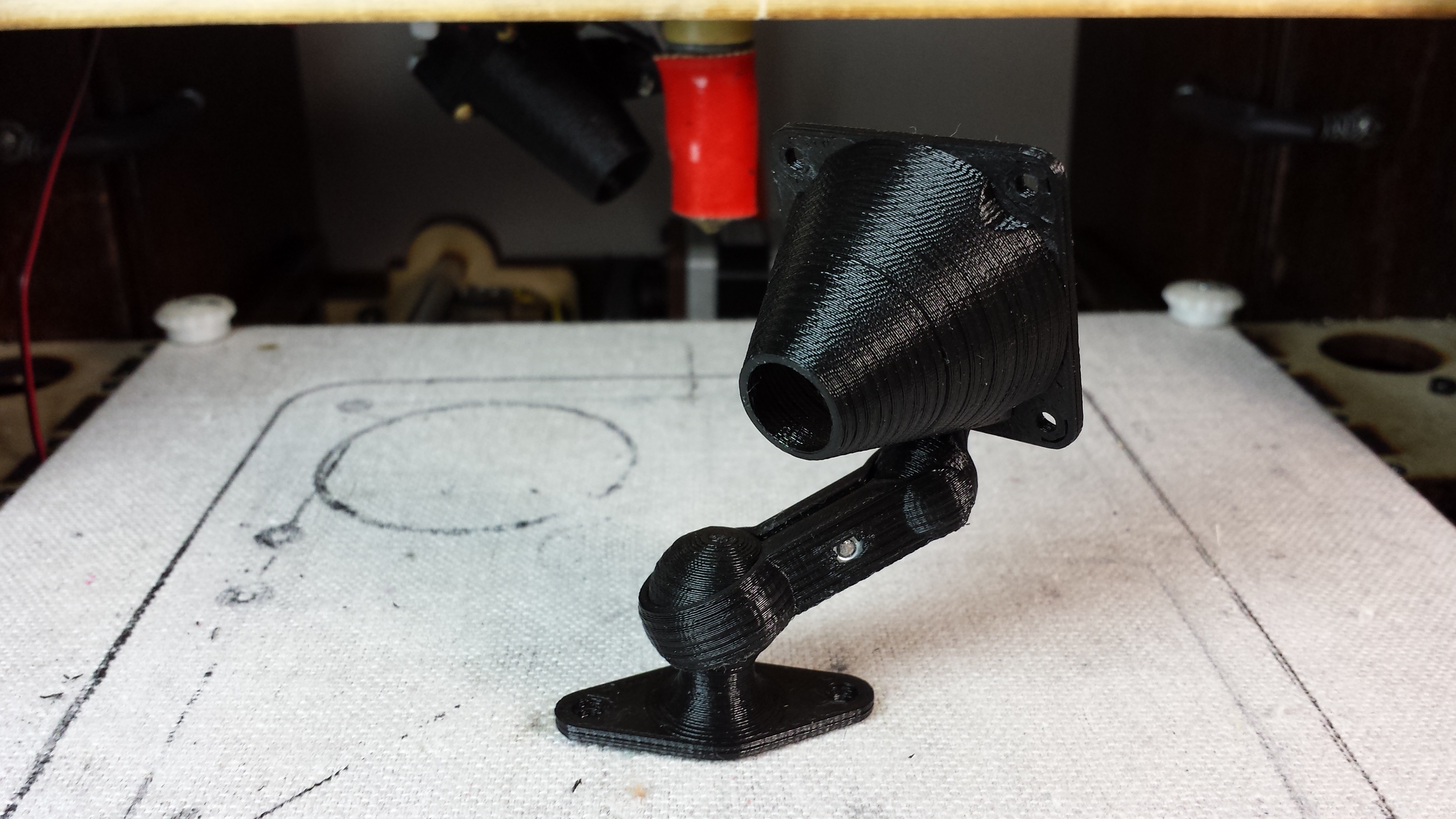
In looking around previously I’d found this cool adjustable mount by RichRap, but since it wasn’t a SCAD file, I didn’t want to spend too much time struggling with importing into OpenSCAD and then attempting to modify the STL to fit my needs. After some mighty wrestling with trigonometry, I was able to sketch out a basic mounted ball joint.

This first version just has two trapped nuts, one for the clamping screw and one to use as a mount for one corner of a fan. I liked this one enough to upload a customizable version to Thingiverse, but found that it didn’t give me enough range of motion to properly direct a fan mounted to the underside of the X axis carriage on the GO. I fought against the idea for a little while, but finally concluded that adding an articulated arm might be necessary.
This would also give me an opportunity to integrate a duct into the design of the arm itself. Since I was limited to a pretty small fan size, I was pretty sure I was going to need a duct to focus and direct the air flow, so integrating the fan duct into the arm seemed like a sensible solution.
Somewhere along the way I had fatigued and broken the leads for my heated bed, so I’ve only been printing in PLA until I get around to rewiring it. And without having a cooling fan yet installed, I was struggling a little bit with VERY slow printing speeds. I’d been having the most luck and ease of use with PLA on an acrylic build platform but eventually suffered from some extreme adhesion related to the slow printing speeds and ended up ruining the acrylic bed (both sides) trying to scrape prints off with sharp utensils.
Since then I’ve been printing on canvas, something that works great for PLA as long as you don’t mind the texture and small fibers it leaves on the bottom of the model.
At any rate, I finally settled on a design and was able to tweak it to a state of functionality and install it to the X axis carriage of the GO. Of course it can also be downloaded from Thingiverse.
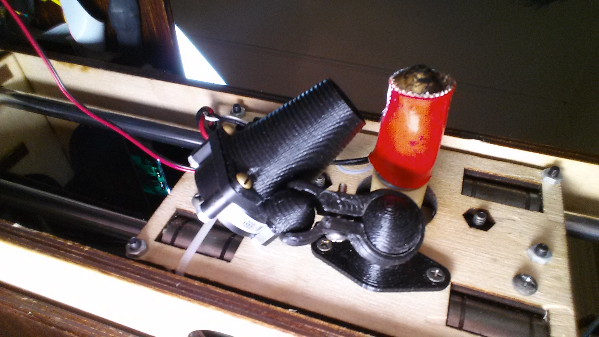
Even with the tiny 25 mm fan it was MUCH easier to print additional iterations, so I ordered a 35 mm fan (the largest I think that would fit) and then printed out a mount, clip and duct for it.
I upgraded the fan to 35 mm and took a couple tries at different ducts to improve airflow (it turns out that a longer duct with a little less “choke” allows better flow than the version pictured here), but I’m still not delighted with the generated wind, so now I’ve ordered two 30 mm fans (the size that seems like an optimal compromise) and will work on a second arm to mount both fans at once. Fingers crossed.
2 thoughts on “printrbot GO – 8 mm rods, GT2 belts, a belt tensioner and a cooling fan”