Don’t just jump in here, start from Part 1!
So we’ve basically got fillet edges on our piece now, but you’ll notice that the actual corners are sharp and not so great looking. To make the corners look consistent with the edges, we’ll need to subtract the exterior of one quarter of a sphere from the corner in the same way we subtracted the exterior of one quarter of a cylinder to get the fillet edge. The code to do such a thing looks like this:
difference () {
    translate([-pad, -pad, -pad]) cube([fRad, fRad, fRad]);
    translate([fRad, fRad, fRad]) sphere(r = fRad+pad);
}
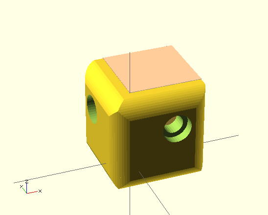
Again, the cube that represents the exterior of the corner is translated off the origin by the amount of our padding in the negative x, y and z directions and is the size of our fillet radius. The sphere itself is the size of our fillet radius plus a bit of padding. If you comment out everything else and paste this into our SCAD, it will look like this.

If we turn this into a module (the way we did with the screw holes and other fillets) and then translate and rotate the call for the module appropriately, the code will look like this.
cSz = 20; //Overall size
tHk = 5; //Thickness
sSd = 4; //Screw shaft diameter
sHd = 6; //Screw head diameter
sHt = 2; //Screw head thickness
e2s = 8; //Edge to screw distance
fPer = 80; //Percentage of thickness to make fillet radius
fRad = tHk * (fPer / 100); //Fillet radius
pad = 0.1; //Padding used to insure manifold

$fn = 0;
$fa = 0.01;
$fs = 0.5;

difference(){
    translate([-tHk, -tHk, -tHk]) cube([cSz, cSz, cSz]);
    #cube([cSz-tHk+pad, cSz-tHk+pad, cSz-tHk+pad]);

    //Add screw holes
    translate ([e2s,-(tHk/2),e2s])
    rotate([-90,0,0])
    screw_hole(); //xz plane screw hole
    translate ([e2s,e2s,-(tHk/2)])
    rotate([0,0,0])
    screw_hole(); //xy plane screw hole
    translate ([-(tHk/2),e2s,e2s])
    rotate([0,90,0])
    screw_hole(); //yz plane screw hole

    //Add fillet edges
    translate([-tHk,-tHk,-tHk])
    rotate([0,0,0])
    fillet(); //z axis fillet
    translate([-tHk,-tHk,-tHk])
    rotate([90,0,90])
    fillet(); //x axis fillet
    translate([-tHk,-tHk,-tHk])
    rotate([-90,-90,0])
    fillet(); //y axis fillet
    translate([-tHk,-tHk,cSz-tHk])
    rotate([0,90,0])
    fillet(); //x axis z offset fillet
    translate([cSz-tHk,-tHk,-tHk])
    rotate([0,0,90])
    fillet(); //z axis x offset fillet
    translate([-tHk,-tHk,cSz-tHk])
    rotate([-90,0,0])
    fillet(); //y axis z offset fillet
    translate([-tHk,cSz-tHk,-tHk])
    rotate([0,0,-90])
    fillet(); //z axis y offset fillet
    translate([-tHk,cSz-tHk,-tHk])
    rotate([180,-90,0])
    fillet(); //x axis y offset fillet
    translate([cSz-tHk,-tHk,-tHk])
    rotate([-90,180,0])
    fillet(); //y axis x offset fillet

    //Add fillet corners
    translate([-tHk, -tHk, -tHk])
    rotate([0,0,0])
    fillet_corner(); //origin corner
    translate([cSz-tHk, -tHk, -tHk])
    rotate([0,0,90])
    fillet_corner(); //x axis corner
    translate([-tHk, -tHk, cSz-tHk])
    rotate([-90,0,0])
    fillet_corner(); //z axis corner
    translate([-tHk, cSz-tHk, -tHk])
    rotate([0,0,-90])
    fillet_corner(); //y axis corner
}

//Creater rounded corners
module fillet_corner() {
    difference () {
        translate([-pad, -pad, -pad]) cube([fRad, fRad, fRad]);
    	translate([fRad, fRad, fRad]) sphere(r = fRad+pad);
    }
};

//Create rounded edges
module fillet() {
    difference() {
        translate([-pad,-pad,-pad])
        cube([fRad, fRad, cSz + (pad * 2)]);
        translate([fRad, fRad, -(pad * 2)])
        cylinder(h = cSz + (pad * 4), r = fRad + pad);
    }
}

//Create screw holes
module screw_hole(){
    union() {
        cylinder(h = tHk+pad, r= (sSd/2), center = true);
        translate([0,0,-((tHk+pad)/2)])
        cylinder(h = sHt, r = (sHd/2));
    }
};
And the results will look like this.
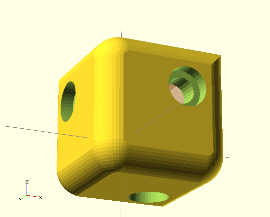
You’ll notice that we’ve left a few of the corners pointy for now. That’s because we’re going to do something fancy with those, but I think that will be an entire post of its own.
One thought on “corner protectors in OpenSCAD (5)”