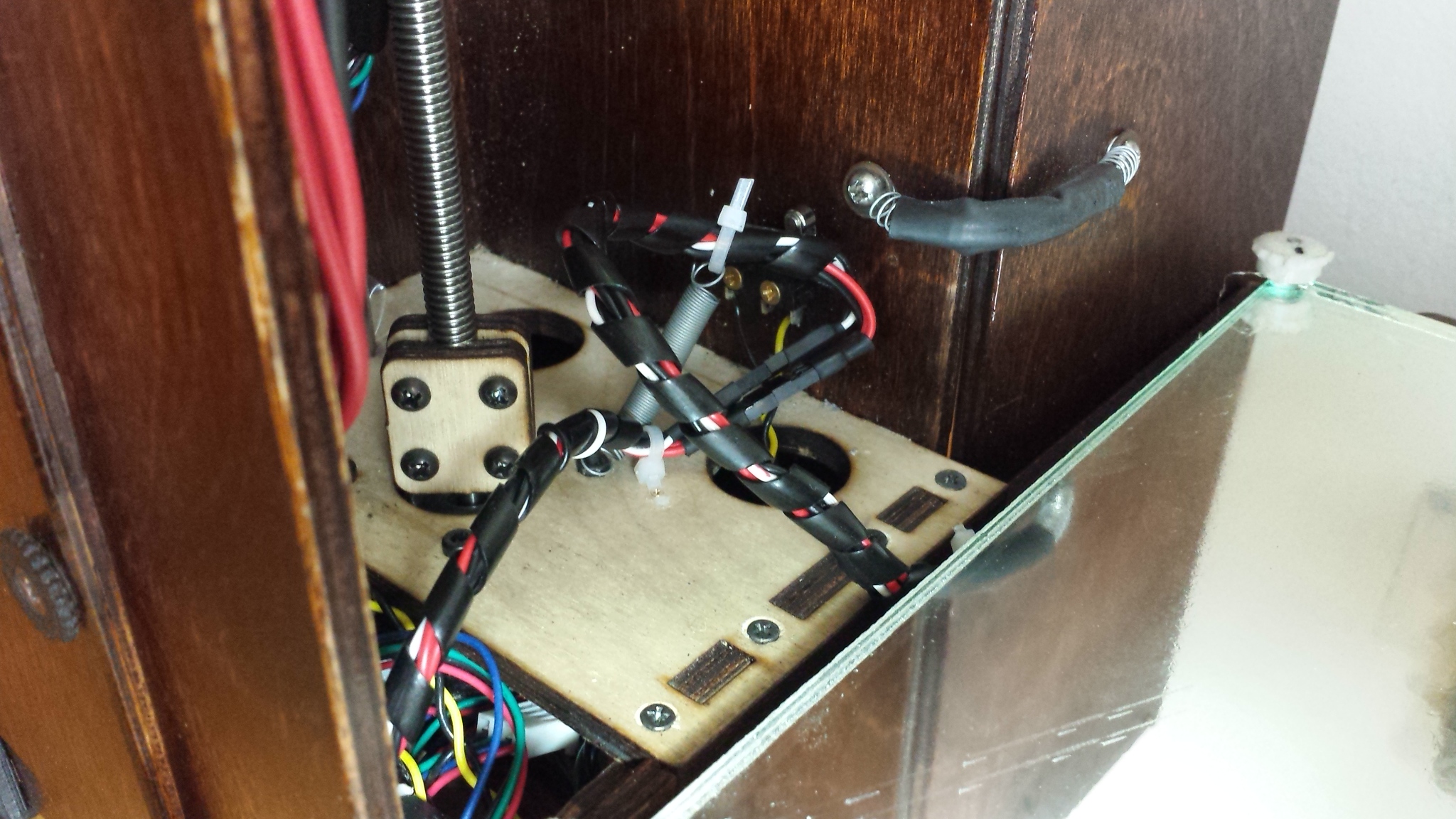
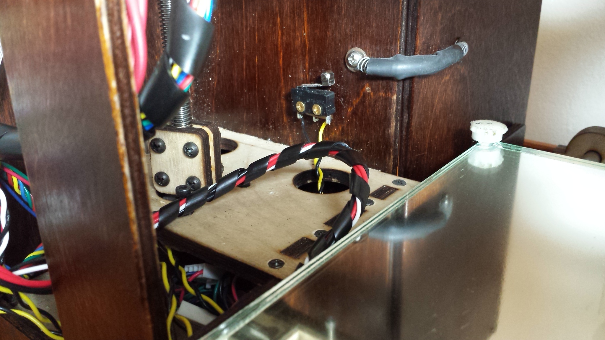
One of the aspects of the initial build of the printrbot GO that I struggled with was how to reliably connect the heated bed. While it seemed sensible to have the wires for the heating element and for the thermistor come out of the side closest to the printrboard itself, keeping those wires appropriately free for the full travel of the bed AND for pulling out the drawer to fold it up into a suitcase yet also out of the way of the hot nozzle and the endstops for the X and Z axes was a bit of an engineering challenge.
After this early failure, I settled on this for a little while.
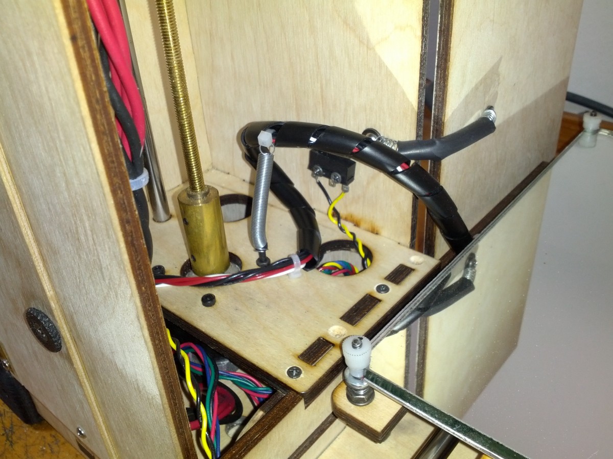
This worked for a good long while, but eventually the wires for the heating element fatigued and failed and I got the opportunity to rethink it again.
I sent an email to printrbot asking for help sourcing the connectors to plug the heating element and the thermistor into the printrboard and, in typical printrbot fashion, they just sent me a complete replacement heated bed. While I was of course grateful for the generous gesture, I wasn’t about to throw out a heated bed that only needed to have new wires soldered to it, so I decided to set aside the new heated bed for my next build (I’d like to help a local high school build a RepRap actually) and continued searching for connectors. Some folks on PrintrbotTalk were able to direct me to the proper connectors for all the printrboard wiring but I decided instead to order a bunch of generic 4 pin, 3 pin and 2 pin male and female connectors from Pololu. I also bought the crimper to attach the male and female pins and a wide variety of colors of wires, also thinking about my next build.
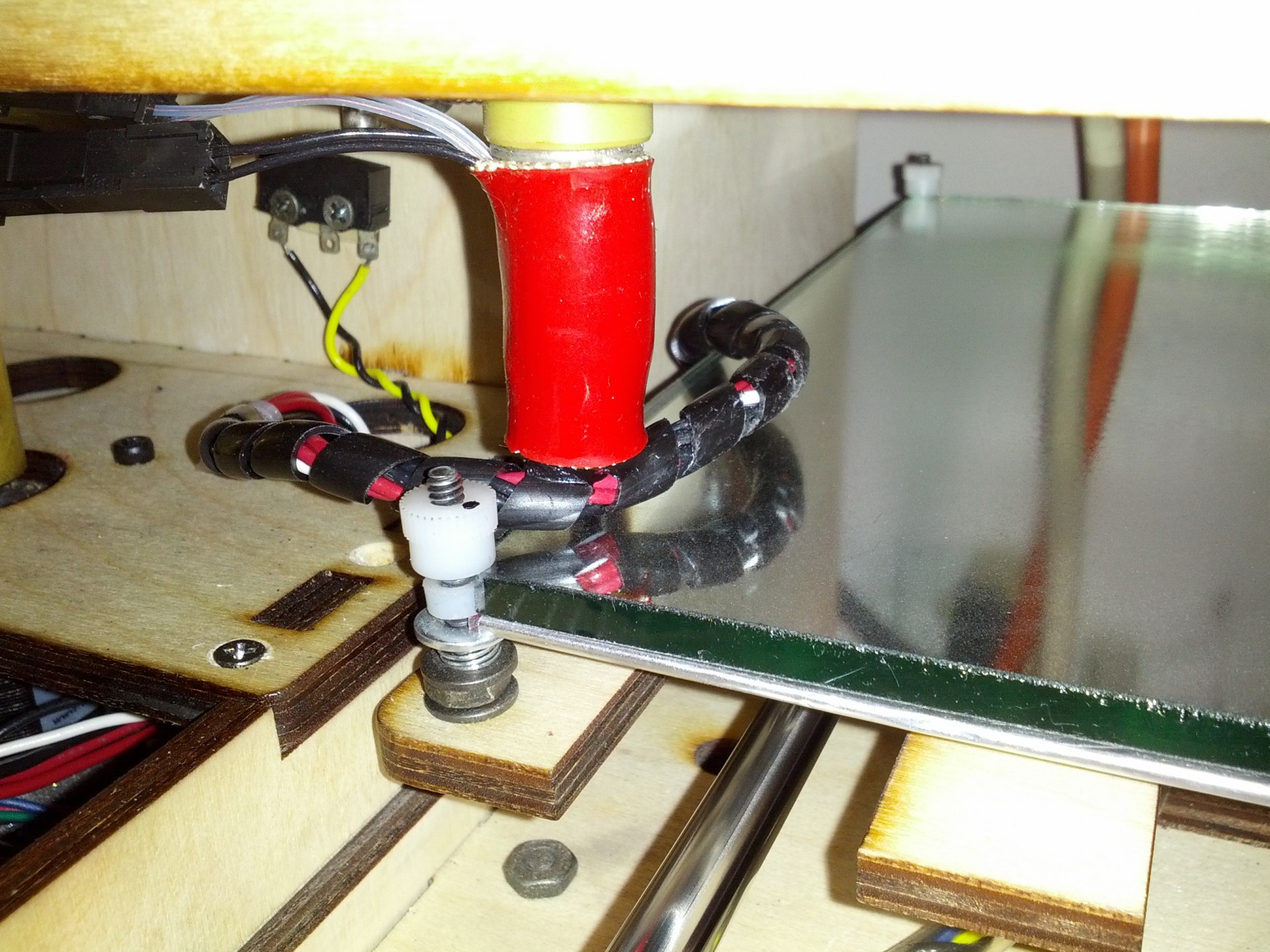
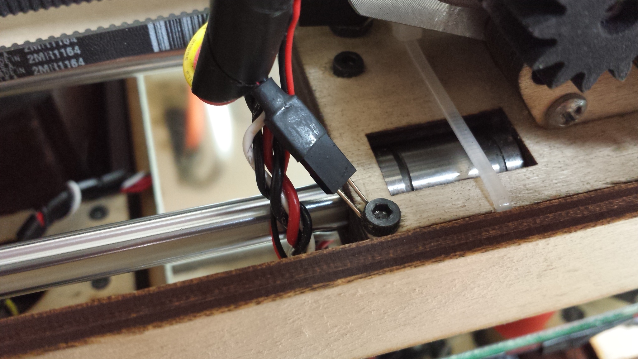
So then I set about replacing the wires from the heated bed and making extension cables for the heated bed and thermistor so that I could more easily unplug them whenever switching out to an unheated bed (in acrylic or canvas for example) and ended up at first with this even more kludgy solution.
This did allow me to unplug the heated bed more easily, but didn’t really keep the wires all that well out of the way of the new fan mount I’d installed. When printing too close to the X=0 portion of the bed for example, the fan mount would routinely run into the semi-stiff wire wrap and upset the angle of the fan.
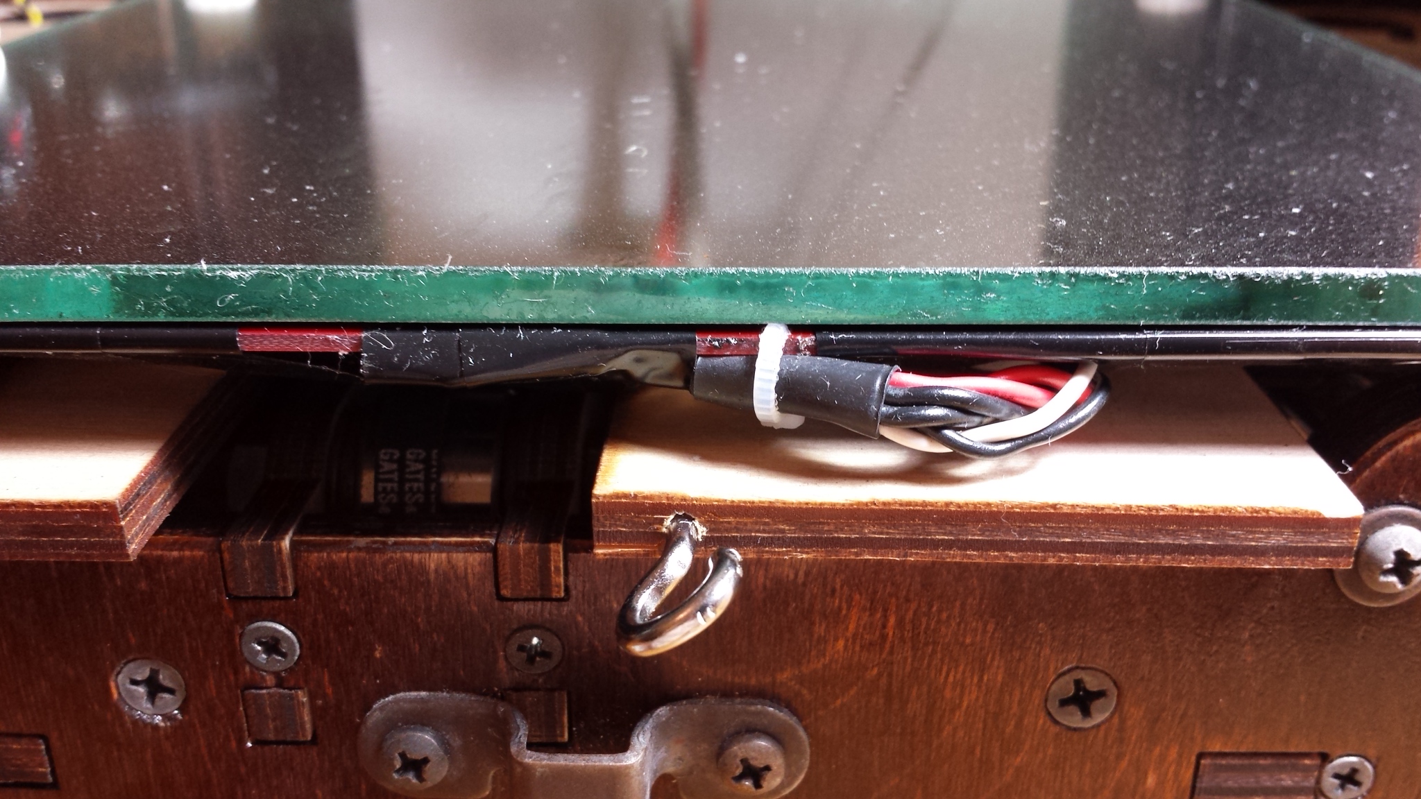
Eventually it occurred to me that the extra length that the extension cables I’d made had given me would allow me to arrange the wires coming out of the heated bed to any orientation I wanted relative to the build platform, so I aligned them towards the very front of the drawer and tucked the cables underneath the Reflectix insulation for the bottom side of the heated bed (bed insulation kit from Jerrill.com) and, for the moment at least, everyone seems happy.
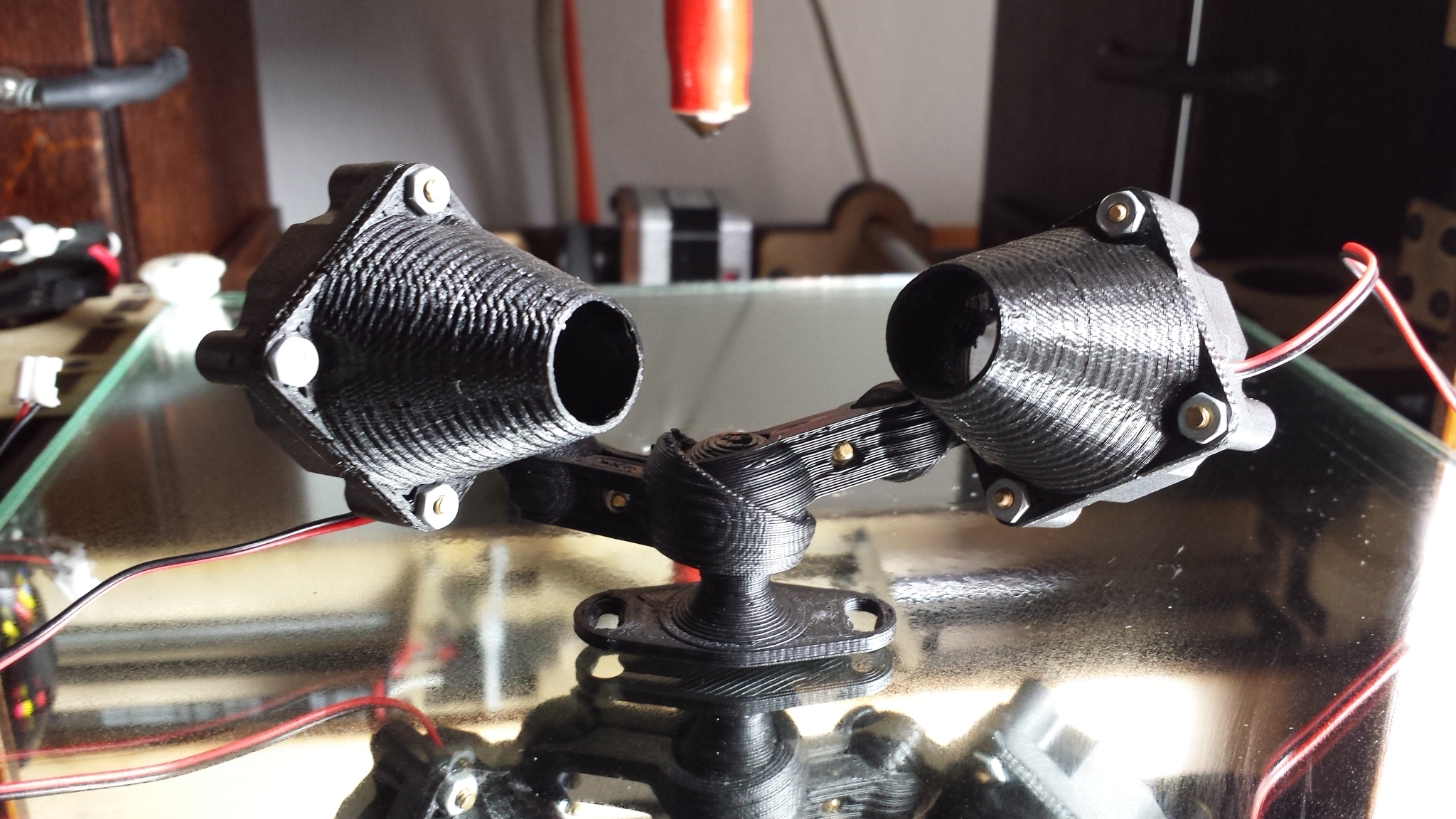
The other thing I needed the custom cabling for was the ability to add a second fan. Actually, I needed an extension cable even to properly install the first fan, it being temporarily wired with extension cables with alligator clips to achieve minimum functionality given the short leads the fans came with. So I used the Pololu connectors to create a Y (parallel) extension cable with two male connectors for the two fans I intended to install and set about augmenting the articulated ball joint fan mount to add a second fan.
Delighted to be printing in ABS again (thanks to the newly re-attached heated bed) I dove into the OpenSCAD design tweaking process and started printing out iteration after iteration of near successes for the first and second clips necessary to add a second fan on a single ball joint mount. Along the way, I had some weird cut outs of the entire bot that seemed like serious trouble and eventually found that the loose male connector for the as-yet-to-be-added second fan had shorted itself across one of the hex bolts that holds the X axis carriage together.
More on that in a moment. So after numerous tweaks and redesigns, I finally settled on this arrangement for my Dual Articulated Ball Joint Fan Mount with Twist-Lock base.
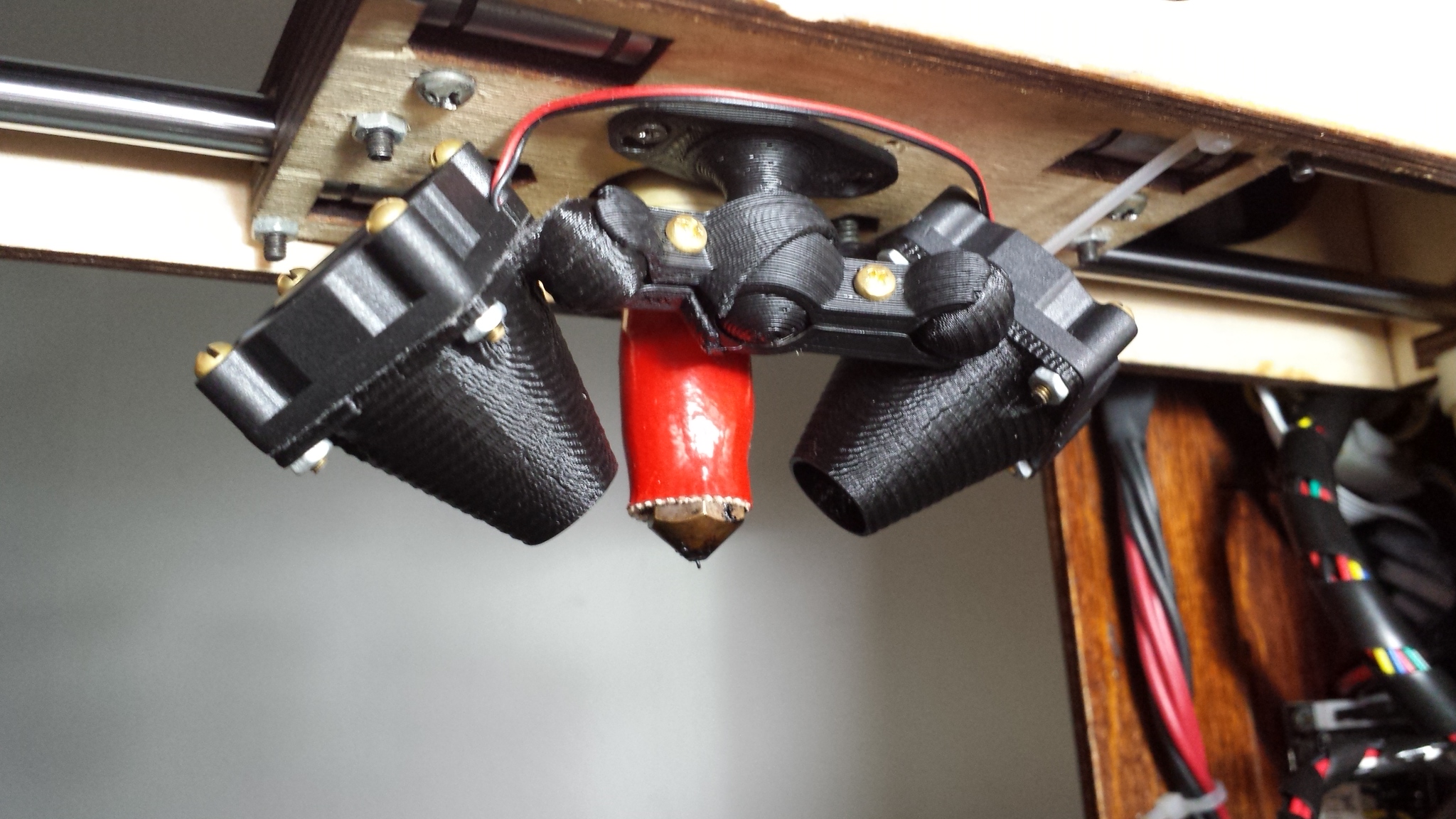
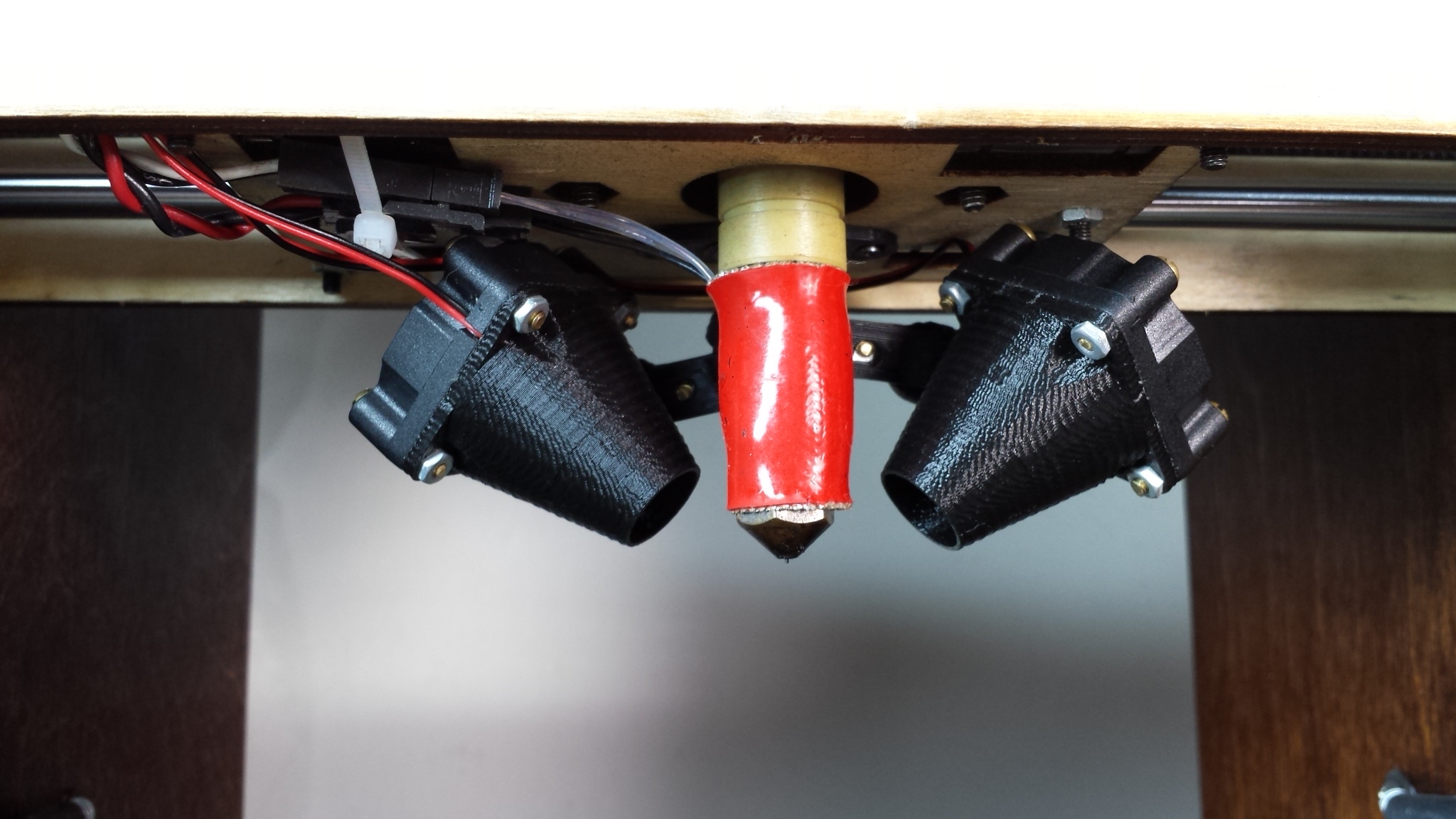 you are not fancy enough for this fan mount
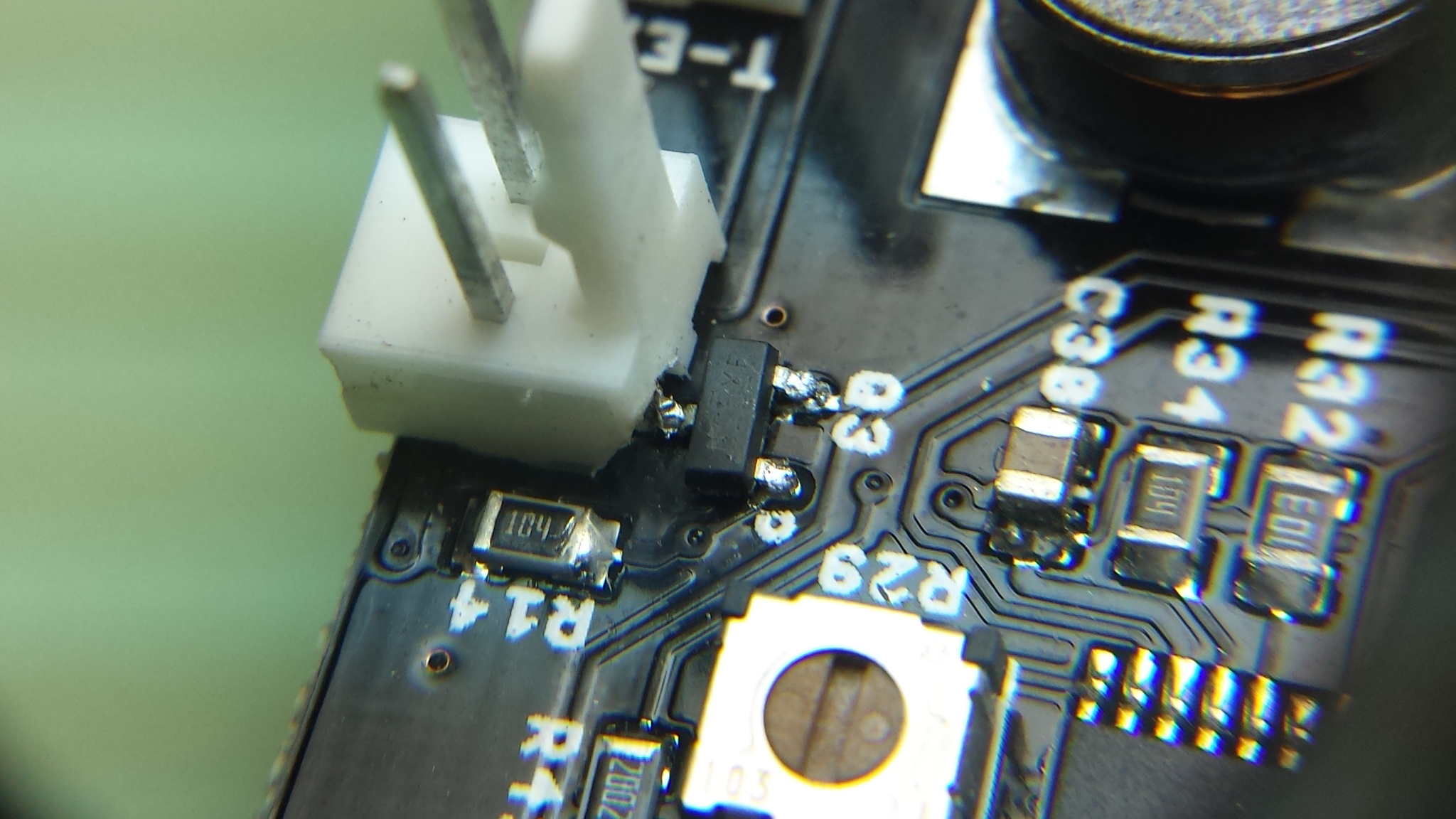
As luck would have it, the shorting action on the male fan connector prior to getting the second fan installed had blown the (very tiny) MOSFET for the fan on the printrboard.
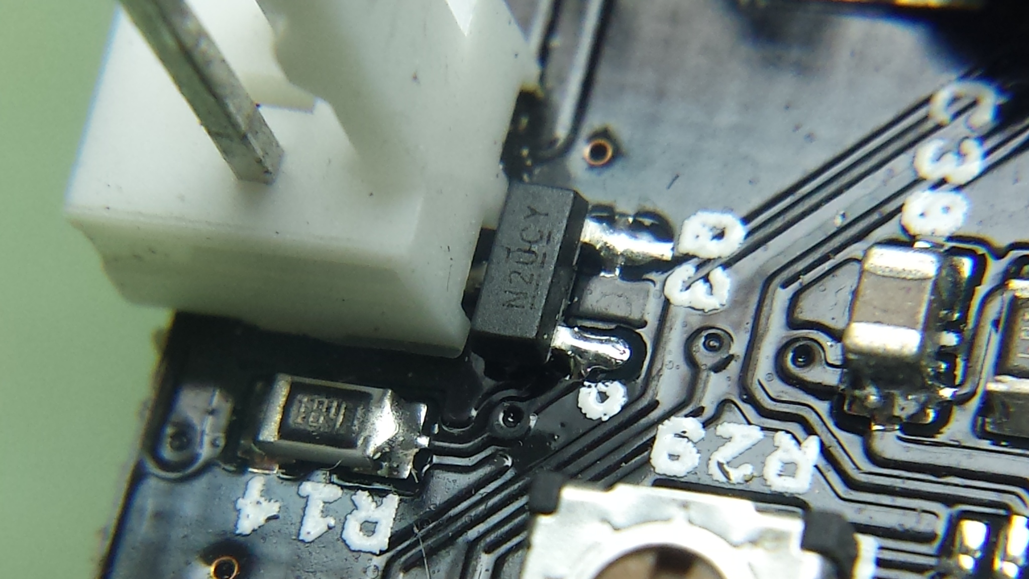
So being the intrepid modder I’ve now become, I ordered a replacement (well, three of them actually; they’re cheap and accidents happen) and went about removing the old one and installing a new one with the help of a stereo microscope (being a watchmaker has some advantages).
I only melted one of the three itty-bitty MOSFETs trying to get it soldered in place and, although I’m not at all proud of the results aesthetically speaking, gosh-darnit if it don’t work.
I have one of the original Kickstarter Printrbot+ units. And… I also just blew that Q3 MOSFET today while messing with a new fan. My fault as I was plugging and unplugging the fan while experimenting with a few different size capacitors across the fan’s pos/neg wires and it blew. Fan is on low all the time now as you described. Thank you for the MOSFET part number. I’m going to attempt the fix, but man it’s small!
Hi, I blew out that same MOSFET for my fan, Q3 on the printrboard.. In my case the fan seemed to have a cold solder joint that came loose and shorted out..
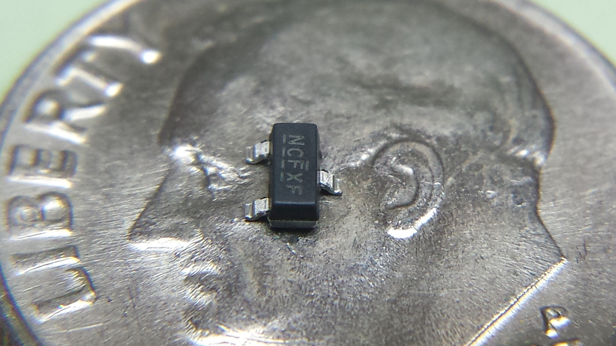
Do you happen to have a part number for it? I have the soldering skills to replace it.. I just need to know what I’m ordering.. I searching for that number NCFXF shown on it on Mouser, Newark and digi-key without any luck..
It’s digi-key part IRLML2060TRPBF. I think I’ve got an extra one though. Drop me a line and I’ll send it to you. ei8htohms at Gmail dot com