I didn’t take a lot of pictures while putting together the X axis assembly as it went mostly without incident and the documentation was pretty good and complete. A few comments about the unexpected however.

This one hole for a wood screw seems to just be in the wrong place. It’s on the left side of the X assembly and if I had planted the screw here, it would’ve just splintered the tab below it since the hole is basically directly over the edge of the material.
It’s worth noting a couple points about all these wood screws. Whenever one purchases large quantities of small screws, you’re bound to get some variety of other screws sprinkled in with the ones you thought you were buying. Some are slightly longer or shorter and some have slightly larger heads. The annoying ones though are the ones that are a slightly larger diameter shaft. They look the same at a glance, but when you try to screw them in they just don’t seem to want to go. And when you’re installing as many wood screws as the GO requires, well that extra annoyance just won’t do. When I come across these oddballs I just set them aside and go on to the next one. I seem to have been provided with plenty of extras but I won’t know for sure until the end I guess (I ain’t counting).
I should also mention if I didn’t already that I pre-drilled all of the holes for the wood screws with a 3/64″ bit. It makes it easier to drive them in, still gives you plenty of “bite” and, most critically, keeps you from splitting the sides of the panels when you’re screwing into them. Since the panels were just cut with a laser cutter, all the holes and shapes are on the flats, with no routing, milling or even holes drilled in the sides. To be expected for this kind of kit I think, but save yourself some grief and add the extra holes yourself.

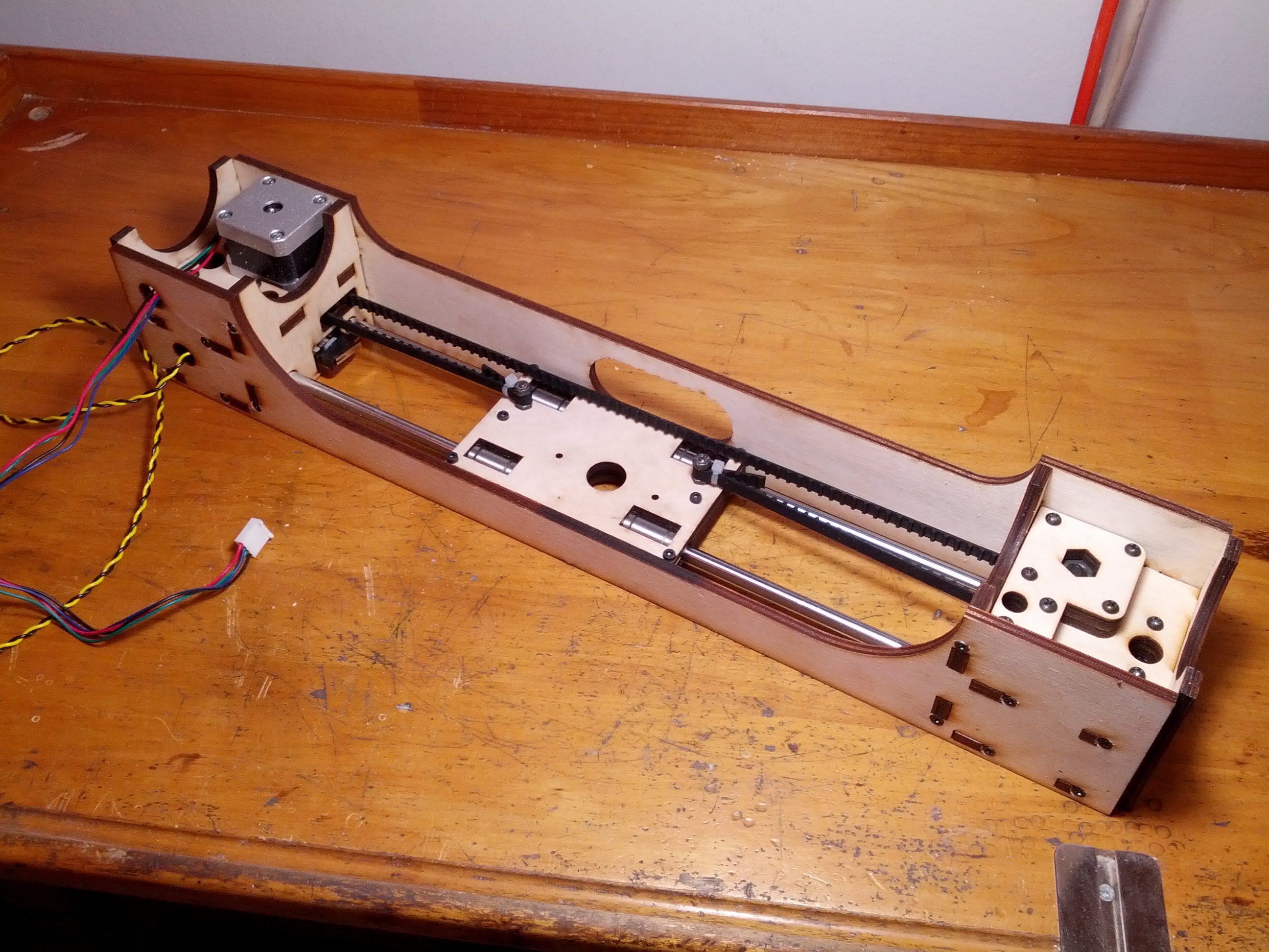
Something else I scratched my head about was the idler for the X axis belt. It’s a ball bearing sandwiched between two “Fender” washers (no idea why they’re called that) on a bolt with the vertical freedom limited by a large nylock nut. You’re meant to keep the nylock nut loose enough so that the washers and the bearing can both spin freely on the bolt and if you tighten it down too much you’ll freeze the bearing between the washers since the bearing is the same width at the hub and at the outer edge and the washers are larger than the bearing.
Spinning loose on a nut is not really how a fancy ball bearing is put to best use, but upon consideration you’ll realize that under tension the hub will mostly stay in place while the bearing spins free. More importantly, the washers are also free to spin, something that will help to reduce friction when the belt rubs on the sides of the washers. I’ve thought about this for a few days and I can’t figure out a better arrangement thus far. The idler for the Y axis belt doesn’t have these large washers (it uses two bearings side by side) but perhaps the singular motion of the carriage on the Y axis makes the belt less prone to creeping from side to side? The Y axis idler is also supported on both sides, something that undoubtedly improves it’s stability while the X axis idler is cantilevered.
There are a couple of fiddly little bits (four of them actually, two on each side) in the X axis assembly that are not easy to secure.
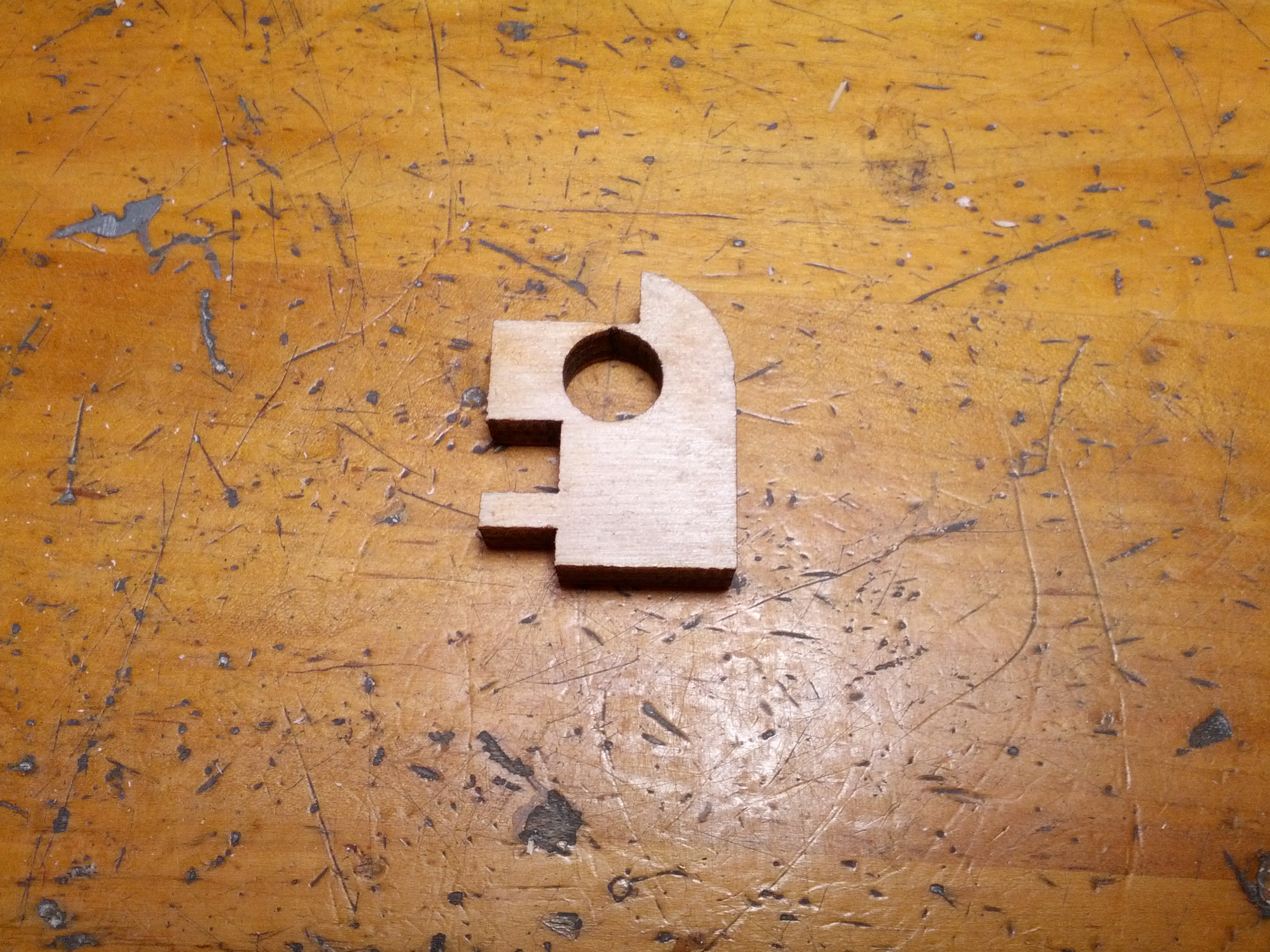
I guess I’d call them brackets for the guide rods. Holding them in place while you sink a wood screw into them is fiddly work. I debated possibly just leaving them loose even. They would stay in place because of the rods and the tabs slotted into the panel above them but would provide minimal support if not anchored by a screw. It’s unclear what kind of support they’ll provide anyway since they’re at the very end of the rods AND there is another hole the rods are going through on each side, but maybe a smidge of vibration control?
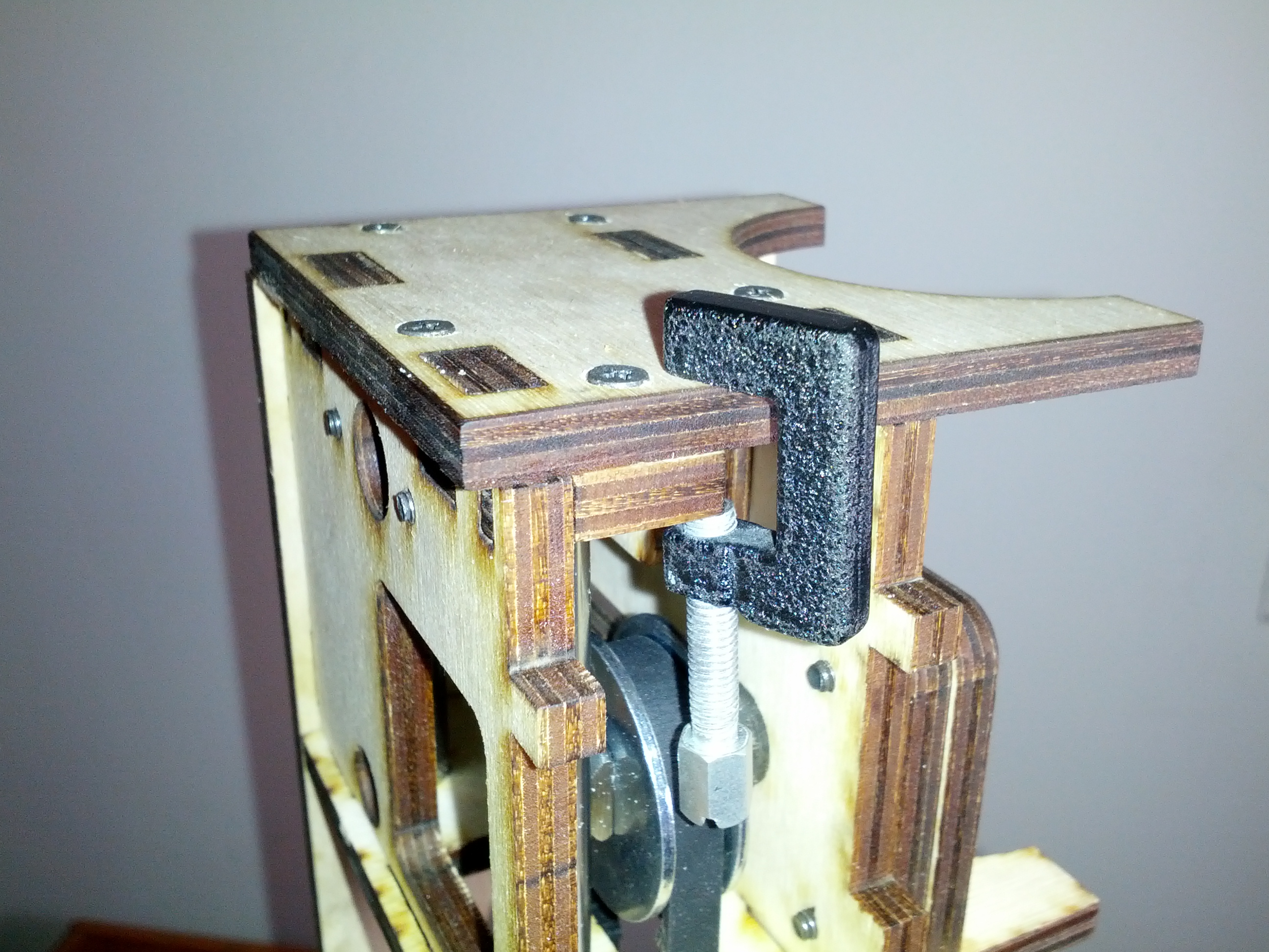
Anyway, I dug up these tiny C-clamps and worked it out.
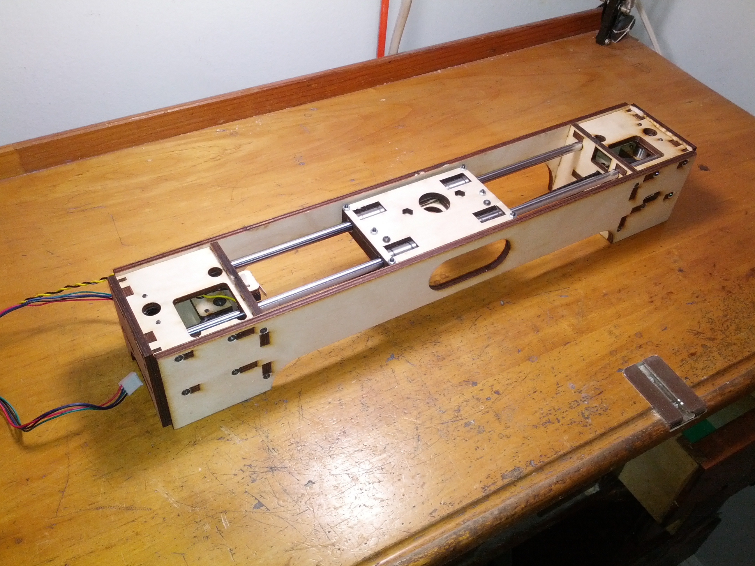
When I got the little boxes for both the right and the left assembled, I fit the guide rods and the carriage for the extruder. The whole thing frankly felt a little twisted to me (like, literally), but the carriage still seemed to move nice and smooth and despite my best efforts to force it into an untwisted position (I think I made it a little better), it never felt quite perfect. This may come back to haunt me down the road, but I don’t know enough to be scared.