Don’t just jump in here, start from Part 1!
Now it’s time for the big finish. For our final decorative flourish, we’re going to put a large rounded corner on each of the three surfaces with screw holes in them, with the radius of the corner determined by how close the screw hole is to the edge. To do this we’ll need to learn a little about rotate_extrude however, one of the niftier if also more confusing OpenSCAD functions I’ve had the pleasure of using. And by the way, if you know a little something about rotate_extrude, please drop me a line and explain it to me!
Before we start further complicating our model though, let me mention that at some point OpenSCAD is going to choke on the compile preview (F5). Mine did so just before inserting the very last big rounded corner at the end of this post. What happens is that OpenSCAD has a built in limit for how many elements it’s willing to show in the compile preview mode, and with the number of objects/surfaces we’re playing with you’ll likely hit that limit like I did. If you click F5 and you get something that looks like this, don’t fear.
This is just OpenSCAD’s attempt to preview something after you’ve hit the limit for elements to compile and preview. The object will still compile and render (F6) properly, but that kinda takes a long time, depending on how fine your resolution ($fs) is set. You can also adjust the default of 2000 elements under Edit – Preferences – Advanced and then OpenSCAD will continue to compile preview properly up to the new limit you’ve set.
Extrusion is what solid modelling software calls it when you take a 2d shape and expand it out into a third dimension. Rotate_extrude can be used to turn a 2d shape into a 3d object by rotating the shape about the z axis. If you use rotate_extrude without any translation, you can make a solid cylindrical object of a variety of shapes. If you add in some translation, you can make various types of donuts. OK, toroids. Whatever.
Try this (after commenting out all of that old stuff we were working on).
rotate_extrude ()
circle(r = fRad+pad);
}
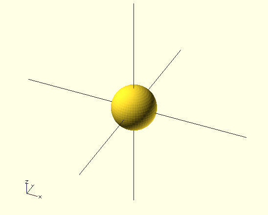
I know, not all that impressive since we already know how to make a sphere. But now let’s try translating out our extrusion also.
rotate_extrude ()
translate([cSz-tHk-e2s-fRad, fRad, 0])
circle(r = fRad+pad);
}
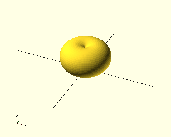
Now that’s something we haven’t seen before: a torus. A pudgy torus without a proper hole in the middle, but still, torus-like indisputably. We’ve told rotate_extrude to place a circle with a radius equal to our fillet radius plus padding at a distance from the origin of the size of our object minus the thickness of our object minus our edge to screw distance minus our fillet radius (phew!) and elevated by the height of our fillet radius and then rotated and extruded it through a full circle (the only way you can rotate_extrude unfortunately) around the z axis. You’ll notice that there’s a third argument in the translate function and if you’re wondering what it’s there for, you’re not alone. The first argument is the distance from the origin perpendicular to the z axis, the second argument is for the height off of the xy plane along the z axis, and the third argument is completely mysterious (to me anyway). If you do know what it’s there for, again, drop me a line!
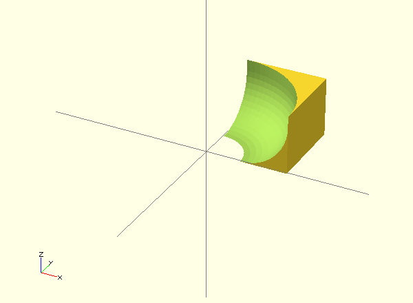
OK, so we’re going to remove one quarter (radially speaking) of one quarter (height-wise) of the exterior of this torus-like object from our prior object to create a large rounded fillet on the corners adjacent to and centered around our screw holes. We’re also going to have to remove one quarter (radially speaking) of a cylinder with a height equal to the difference between our fillet radius and our object thickness to fully occlude the rest of the corner too (in case our fillet radius is less than 100% of the thickness).
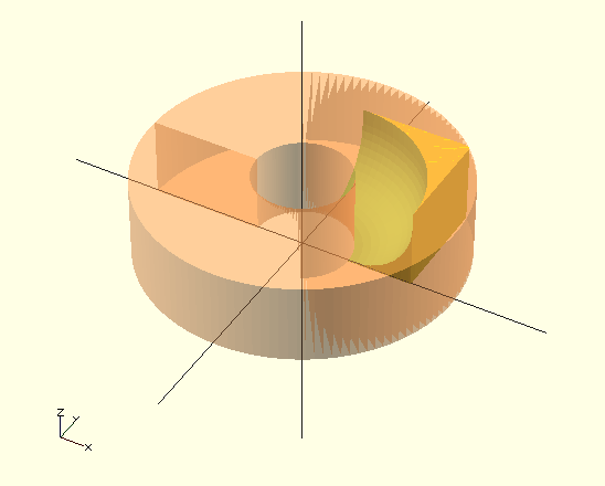
I know, I’m losing you here. Unfortunately it gets a little stickier still. There are two ways to go at this juncture, and one of them gets even more mathy, so I’m just gonna gesture vaguely in that direction and then go the other way in the hopes of making things slightly easier to follow (the key word here being “slightly”). You see, we need to define the exterior of this torus we’re playing with, but a torus has an exterior portion that’s inside of its donut hole also and we don’t want to leave that in either. We can either occlude that by subtracting our torus from an appropriately sized and translated square that has been rotate_extruded also (and then find where these two components overlap (using the as yet unseen intersection function) a cuboid that represents only one quarter of the two toroidal objects in question, as seen here), OR we can simply subtract a cylinder with a radius from the origin to the center point of the toroidal tube (if you will) in addition to the torus itself from the aforementioned cuboid (so that we’re still only looking at one quarter of the cylinder (cylinders if you include the little squatty one referenced in the preceding paragraph) and torus in question). The code for the latter option looks like this (I did mention this was the easier one, right?).
difference() {
    translate([0,0,-pad])
    cube([cSz-tHk-e2s+pad,cSz-tHk-e2s+pad,tHk+pad*2]); /*This is a cuboid large enough to cover the corner of our object from the center of our screw hole to the tip of the corner plus a little padding on both sides*/
    translate([0,0,-pad*2])
    cylinder(r = cSz-tHk-e2s-fRad, h = tHk+pad*4); /*This is the small/tall cylinder that will occlude the center of the donut*/
    rotate_extrude ()
    translate([cSz-tHk-e2s-fRad, fRad, 0])
    circle(r = fRad+pad);
    translate([0,0,fRad])
    cylinder(r =  cSz-tHk-e2s+pad,h = tHk-fRad+pad*2); /*This be the large/short cylinder to make up for the difference between our fillet radius and the thickness of our object*/
};
The former option seems more elegant to my mind in some perverse way, but it requires us to either make our rotate_extruded cuboid arbitrarily large (to insure complete corner coverage – NOT elegant) or to use some Pythagorean geometry to calculate its size precisely, and it’s hard to justify the extra math when the end result is exactly as good as what we’ve done above with a little less fuss.
Please paste the above code in and put the number sign (# – did you know this is also called an octothorp?) in before the various components to see exactly where they are and what they look like. There’s no point in this not being a tutorial if you’re not going to not learn something along the way rather than just copying and pasting the end results (not?). You’ll notice that I’ve also snuck in a method for writing in multi-line comments. Instead of just using //, you can place your /*comments*/ between a slash-asterisks and asterisks-slash combination to make them arbitrarily long.
So now all that remains is to make this big round corner into a module (why not let’s call it big_round_corner?) and then remove it selectively from our object just like we did with our fillet edges and fillet corners. Without the longish comments, something like this.
//Create a big, rounded, fillet corner around the screw holes
module big_round_corner() {
    difference() {
        translate([0,0,-pad])
        cube([cSz-tHk-e2s+pad,cSz-tHk-e2s+pad,tHk+pad]);
        translate([0,0,-pad*2])
        cylinder(r = cSz-tHk-e2s-fRad, h = tHk+pad);
        rotate_extrude ()
        translate([cSz-tHk-e2s-fRad, fRad, 0])
        circle(r = fRad+pad);
        translate([0,0,fRad])
        cylinder(r =  cSz-tHk-e2s+pad,h = tHk-fRad+pad);
    }
};
When we place the module calls as three more additional children in our already large family looked over by our grand patron difference function, our code will look like this.
cSz = 20; //Overall size
tHk = 5; //Thickness
sSd = 4; //Screw shaft diameter
sHd = 6; //Screw head diameter
sHt = 2; //Screw head thickness
e2s = 8; //Edge to screw distance
fPer = 80; //Percentage of thickness to make fillet radius
fRad = tHk * (fPer / 100); //Fillet radius
pad = 0.1; //Padding used to insure manifold

$fn = 0;
$fa = 0.01;
$fs = 0.5;

difference(){
    translate([-tHk, -tHk, -tHk]) cube([cSz, cSz, cSz]);
	 cube([cSz-tHk+pad, cSz-tHk+pad, cSz-tHk+pad]);

    //Add screw holes
    translate ([e2s,-(tHk/2),e2s])
    rotate([-90,0,0])
    screw_hole(); //xz plane screw hole
    translate ([e2s,e2s,-(tHk/2)])
    rotate([0,0,0])
    screw_hole(); //xy plane screw hole
    translate ([-(tHk/2),e2s,e2s])
    rotate([0,90,0])
    screw_hole(); //yz plane screw hole

    //Add fillet edges
    translate([-tHk,-tHk,-tHk])
    rotate([0,0,0])
    fillet(); //z axis fillet
    translate([-tHk,-tHk,-tHk])
    rotate([90,0,90])
    fillet(); //x axis fillet
    translate([-tHk,-tHk,-tHk])
    rotate([-90,-90,0])
    fillet(); //y axis fillet
    translate([-tHk,-tHk,cSz-tHk])
    rotate([0,90,0])
    fillet(); //x axis z offset fillet
    translate([cSz-tHk,-tHk,-tHk])
    rotate([0,0,90])
    fillet(); //z axis x offset fillet
    translate([-tHk,-tHk,cSz-tHk])
    rotate([-90,0,0])
    fillet(); //y axis z offset fillet
    translate([-tHk,cSz-tHk,-tHk])
    rotate([0,0,-90])
    fillet(); //z axis y offset fillet
    translate([-tHk,cSz-tHk,-tHk])
    rotate([180,-90,0])
    fillet(); //x axis y offset fillet
    translate([cSz-tHk,-tHk,-tHk])
    rotate([-90,180,0])
    fillet(); //y axis x offset fillet

    //Add fillet corners
    translate([-tHk, -tHk, -tHk])
    rotate([0,0,0])
    fillet_corner(); //origin corner
    translate([cSz-tHk, -tHk, -tHk])
    rotate([0,0,90])
    fillet_corner(); //x axis corner
    translate([-tHk, -tHk, cSz-tHk])
    rotate([-90,0,0])
    fillet_corner(); //z axis corner
    translate([-tHk, cSz-tHk, -tHk])
    rotate([0,0,-90])
    fillet_corner(); //y axis corner

    //Add big round corners
    translate([e2s, e2s, -tHk])
    rotate([0,0,0])
    big_round_corner(); //on xy plane
    translate([e2s, -tHk, e2s])
    rotate([-90,-90,0])
    big_round_corner(); //on xz plane
    translate([-tHk, e2s, e2s])
    rotate([90,0,90])
    big_round_corner(); //on yz plane
}

//Create a big, rounded, fillet corner around the screw holes
module big_round_corner() {
    difference() {
        translate([0,0,-pad])
        cube([cSz-tHk-e2s+pad,cSz-tHk-e2s+pad,tHk+pad*2]);
        translate([0,0,-pad*2])
        cylinder(r = cSz-tHk-e2s-fRad, h = tHk+pad*4);
        rotate_extrude ()
        translate([cSz-tHk-e2s-fRad, fRad, 0])
        circle(r = fRad+pad);
        translate([0,0,fRad])
        cylinder(r =  cSz-tHk-e2s+pad,h = tHk-fRad+pad*2);
    }
};

//Create rounded corners
module fillet_corner() {
    difference () {
        translate([-pad, -pad, -pad]) cube([fRad, fRad, fRad]);
    	translate([fRad, fRad, fRad]) sphere(r = fRad+pad);
    }
};

//Create rounded edges
module fillet() {
    difference() {
        translate([-pad,-pad,-pad])
        cube([fRad, fRad, cSz + (pad * 2)]);
        translate([fRad, fRad, -(pad * 2)])
        cylinder(h = cSz + (pad * 4), r = fRad + pad);
    }
}

//Create screw holes
module screw_hole(){
    union() {
        cylinder(h = tHk+pad, r= (sSd/2), center = true);
        translate([0,0,-((tHk+pad)/2)])
        cylinder(h = sHt, r = (sHd/2));
    }
};
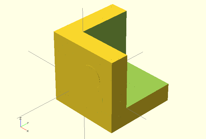
And our fully rendered object will look something like this.
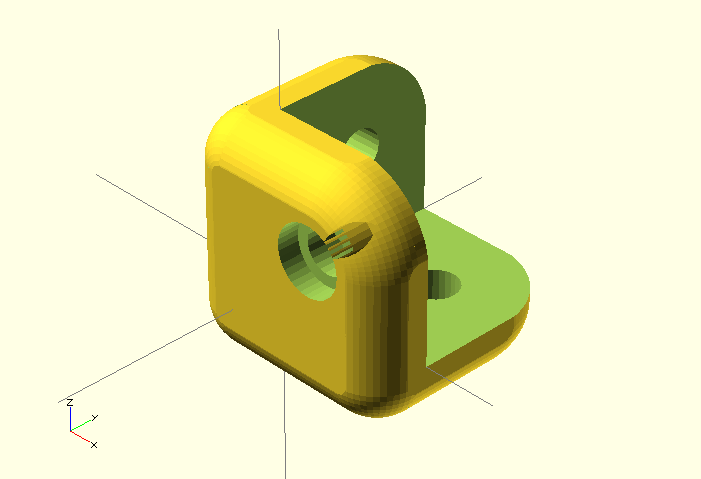
Wait, what’s up with that weirdness visible through the skin of the corner closest to us? I don’t know either, but it’s some kind of artifact of the compile preview and not present when we actually render the object (using F6). 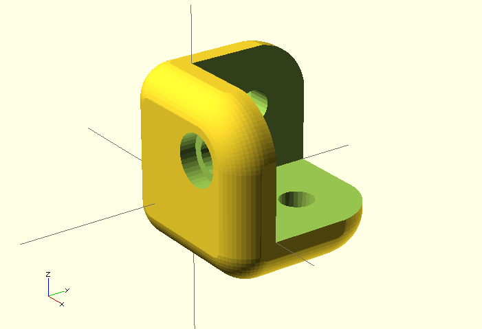
If you made it this far, I hope you enjoyed or at least learned something along the way!
Download the thing here.