Ok, it’s time to man up and say I was wrong. Soo wrong.
The intial test prints after installing my cheapie Oldham couplers were glorious. They represented such a dramatic improvement over my previous prints as far as Z wobble goes that I was convinced that I’d found the be-all-end-all solution for Z wobble. I’d been using them for about a week when I started to notice some strange Z artifacts creeping back into my prints however. The layers were shifting along the Y axis as before, but not in any predictable manner that I could ascertain. The frustrating part was that I was trying to make some prototypes of some jigs for work that require relatively exacting dimensions and some of them were turning out fine and others had too much layer shift to be useful at all.
I was still convinced at that point that the Oldham couplers were not to blame, so I started thinking about skipped steps in either the motor itself or in the stepper driver for the Y axis. I had dialed in the stepper driver current just recently, but the process had not filled me with the greatest confidence all things considered, so I twiddled the pot on the Y axis stepper driver some more but with no observable changes. Still pondering motor problems, I started to get ambitious.
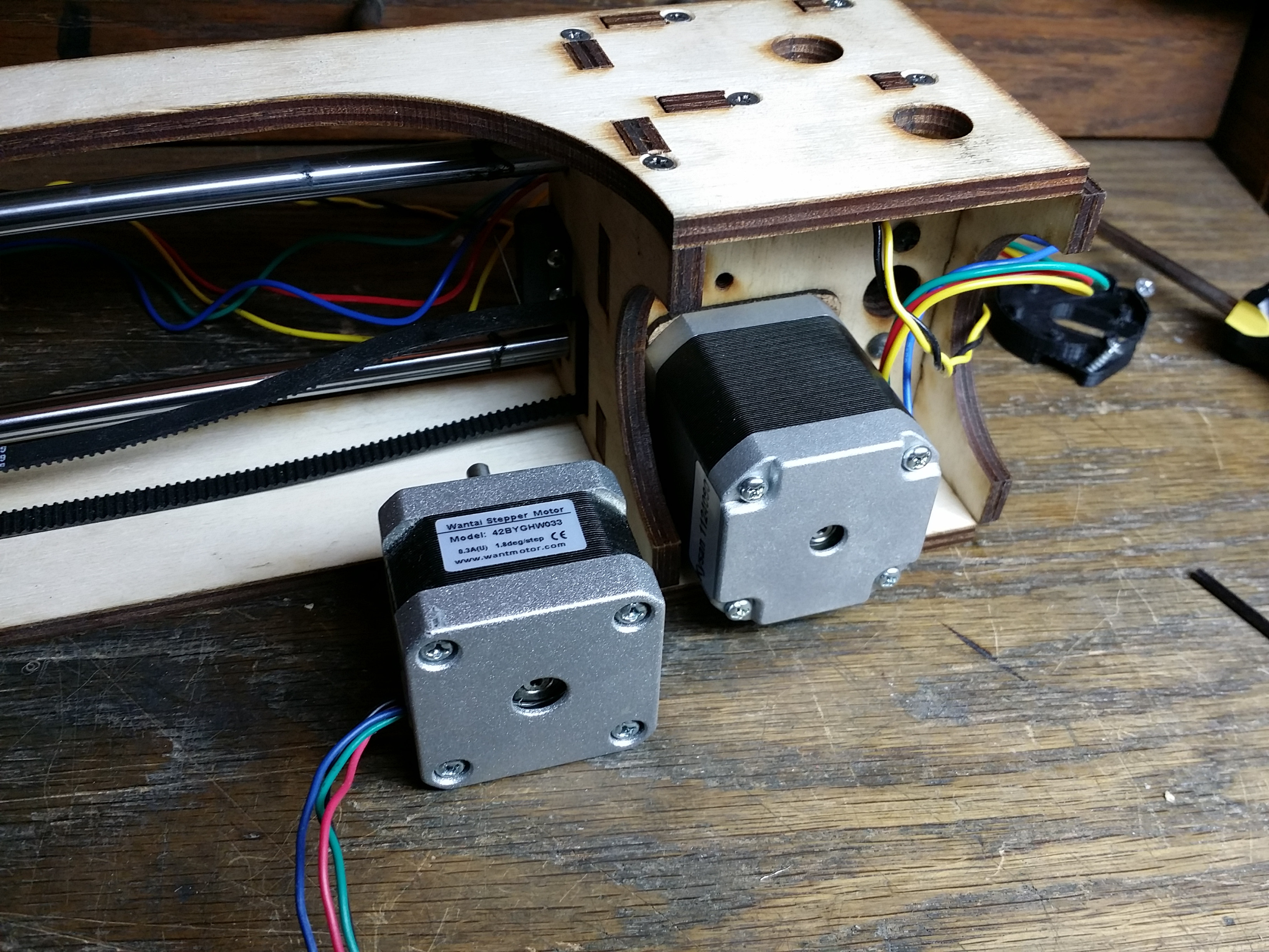
I tore apart my Y axis and modified the panels to install a larger, Kysan motor. Printrbot had sent me four Kysans with the kit when I purchased it by mistake and then when they sent me the Wantai motors that the design actually specified they told me to just keep the Kysans. Since the Wantais always seemed slightly under-powered for the build size of the GO, I had been planning for some time to upgrade to Kysans for the Y and X axes at least (I figure two Wantais on the Z axis is probably sufficient since that axis doesn’t get near as much action as the other axes).
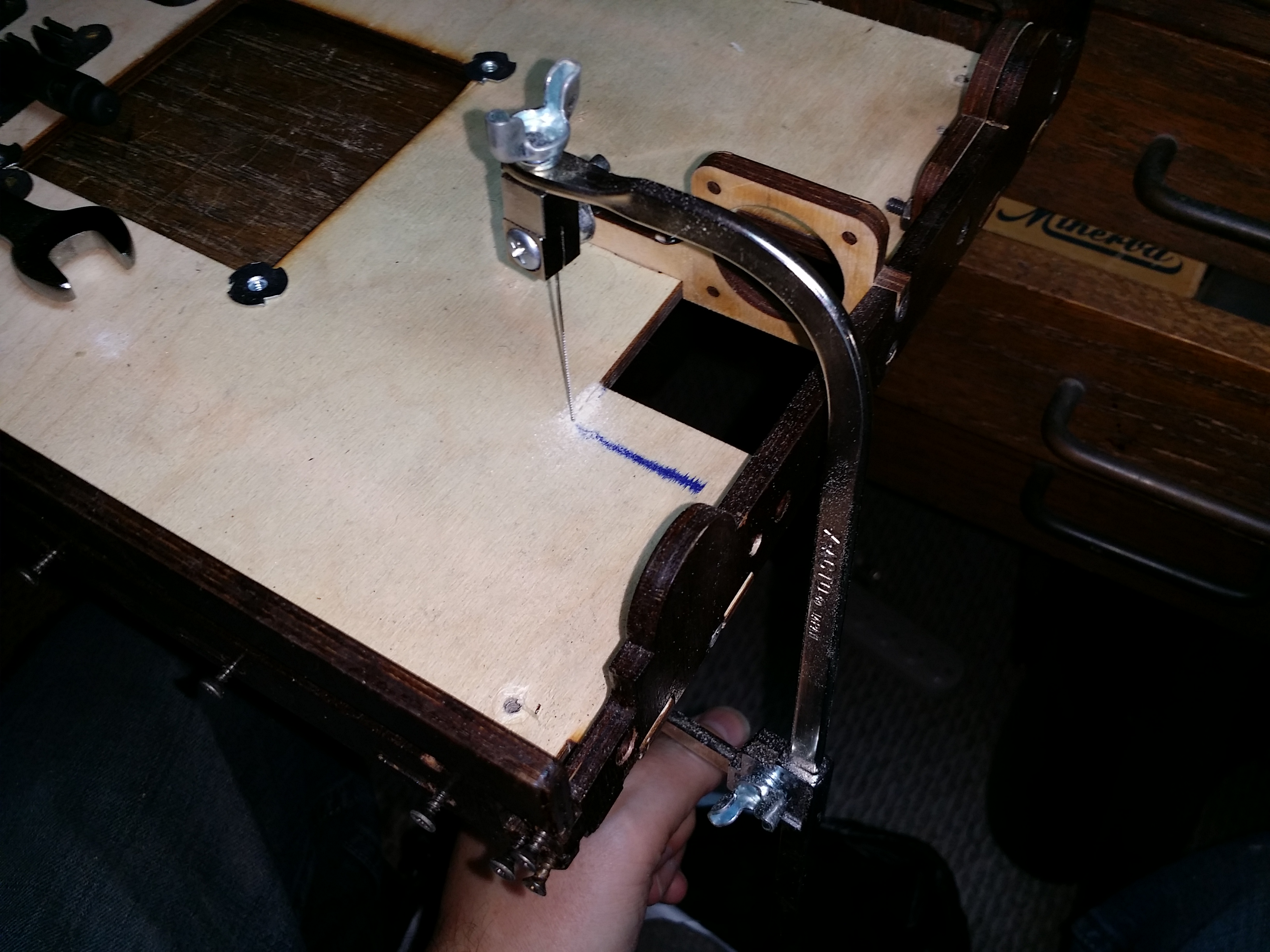
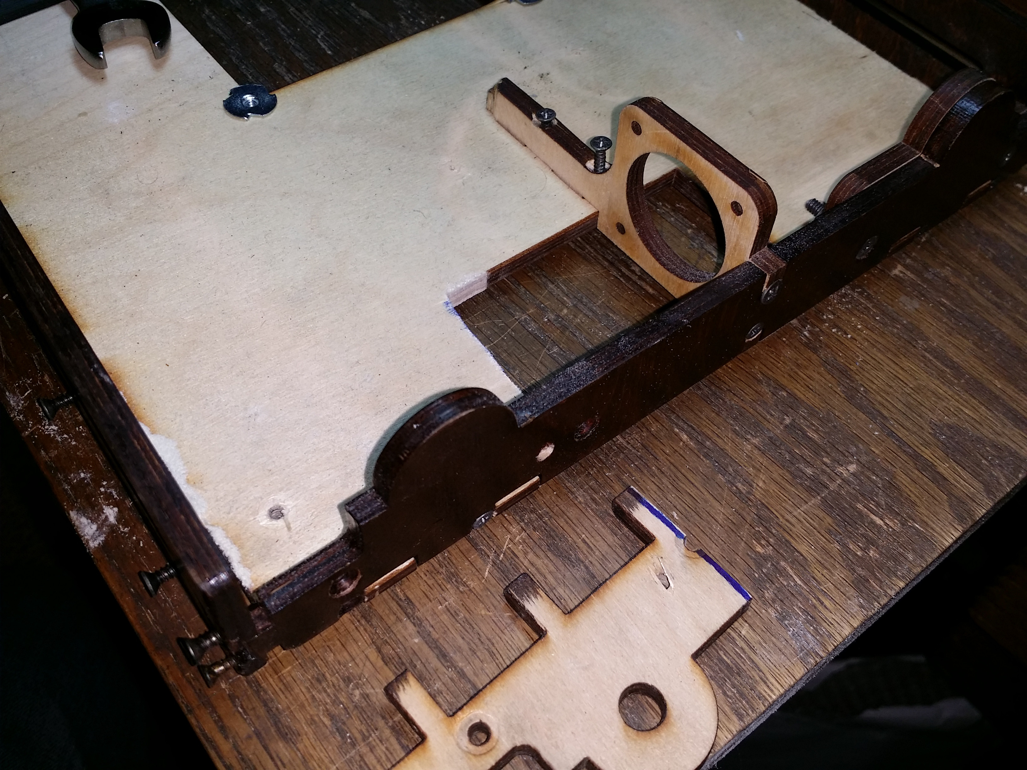
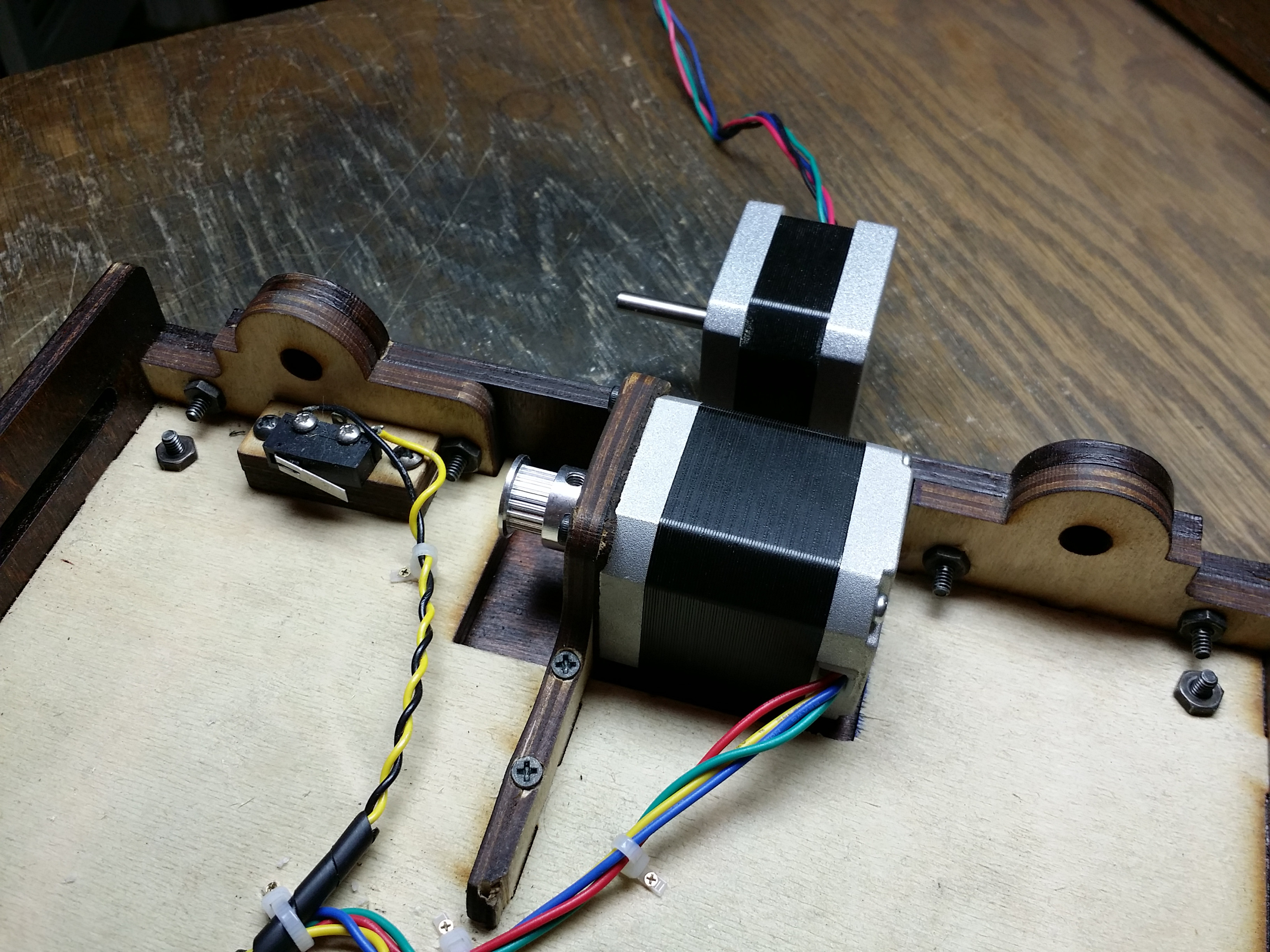
In the first two pictures above you can see that I also added t-nuts to better secure the “hatch” in the bottom of the drawer (I later ground the inside corners of the t-nuts to match the profile of the opening) and I also upgraded the Y-axis belt tensioner from silver PLA to black ABS to better match all the other modded parts on the bot and give it a little more strength (over time I had found that the PLA kind of sagged and shifted; being right underneath the heated bed (only 1/4″ piece on plywood in between), with a glass transition temperature for PLA of only about 60° C and the bed sometimes running at 110° C and all). I also installed a 3dp Aftermarket stepper damper that Brent had given me when I met him at 3d Print Show NYC recently. Of yeah, and a smaller, aluminum GT2 pulley (I had 36 tooth injected molded pulleys previously and I figured the 20 tooth Al pulleys should give me better torque).
Completely unrelated to my Y-axis layer shifting problem I decided to go ahead and upgrade the X-axis motor at the same time. It was MUCH simpler being basically a drop-in and of course I installed the stepper damper and Al pulley there as well.
The new motors had a very nice, burly hum to them and I was feeling pretty good about things except that my damn layer shifting problem was still there. I started to suspect that the Oldham couplers might be the problem after all (gasp!), but it turned out to be more than just that.
It does seem that the internal friction in the Oldham couplers is great enough that they will bind slightly and then slip, and essentially in an unpredictable manner. This must have only started happening after they broke in a little bit, because I can’t figure out otherwise why it didn’t seem to affect the initial test prints. I experimented with installing different types of up and down jogs in the Z axis between layers to see if I could force the couplers to settle a little bit, but this was a no go despite my best efforts.
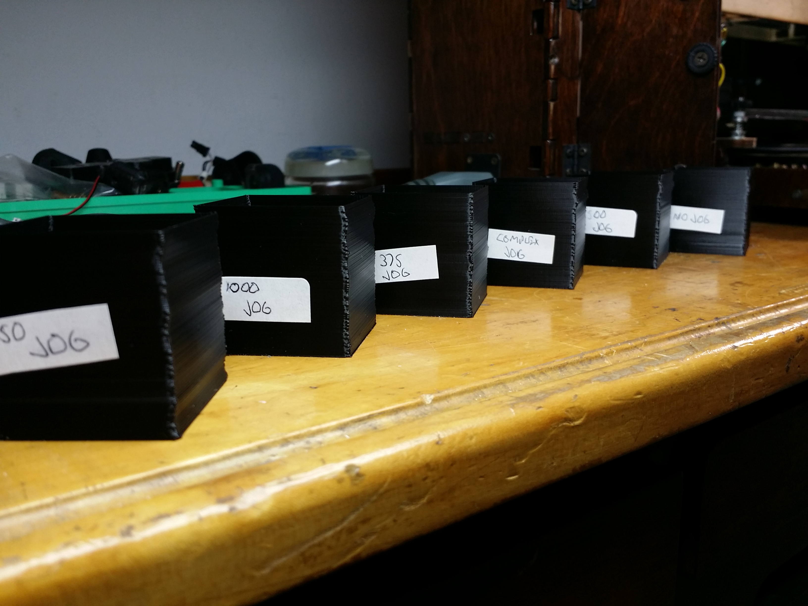
I programmed in a simple jog up and down of 1500, 1000, 750 and 375 microns (one rotation of my Z rods is 1500 microns) and then even tried some exotic jogs like 2400 up, 1200 down, 1800 up and 3000 down between each layer, but with no substantial improvements observed. Then I noticed that each of the test cubes had the same sort of shift near the top and when watching it print realized that the wire wrap for the gantry wiring was rubbing one of the power connectors inside the bot and causing that shift.
It became clear at that point that not only were the Oldham couplers not really helping sufficiently, but the bearings for the smooth vertical rods in the gantry were allowing way too much wobble in general and I’d have to do something dramatic to address it.
I’ve been doing LOTS of thinking on this problem since then and have come to the following conclusions: The nuts for the threaded rods should be at the same height as the bearings for the smooth rods to minimize the amount of leverage that any movement introduced by the theaded rods has on the bearings. More importantly still, the tip of the nozzle should also be at the same height as the bearings so that any tilting in the bearings that does occur should leave the tip of the nozzle as stationary as possible. And most important of all, the gantry should be properly constrained on the Z axis smooth rods: one linear ball bearing on each side is just not going to cut it.
So my plan now is to perform the architectural upgrade to the gantry I’d been contemplating previously to add additional bearing blocks below the ones that it has currently (closer to the height of the nuts and the tip of the nozzle). Brook sent me the original Printrbot GO design files, so I plan to modify a few of the pieces for the gantry (assuming I can figure out how to open and edit them – they’re AI files and I don’t have Adobe Illustrator) and then find a local shop to laser cut some replacement panels for me upon which to affix some aluminum bearing blocks for LM8UU bearings. I may even go so far at that point as to install anodized aluminum rods and Dry-Lin bushings from Igus for (presumably) even greater stability. We’ll see.
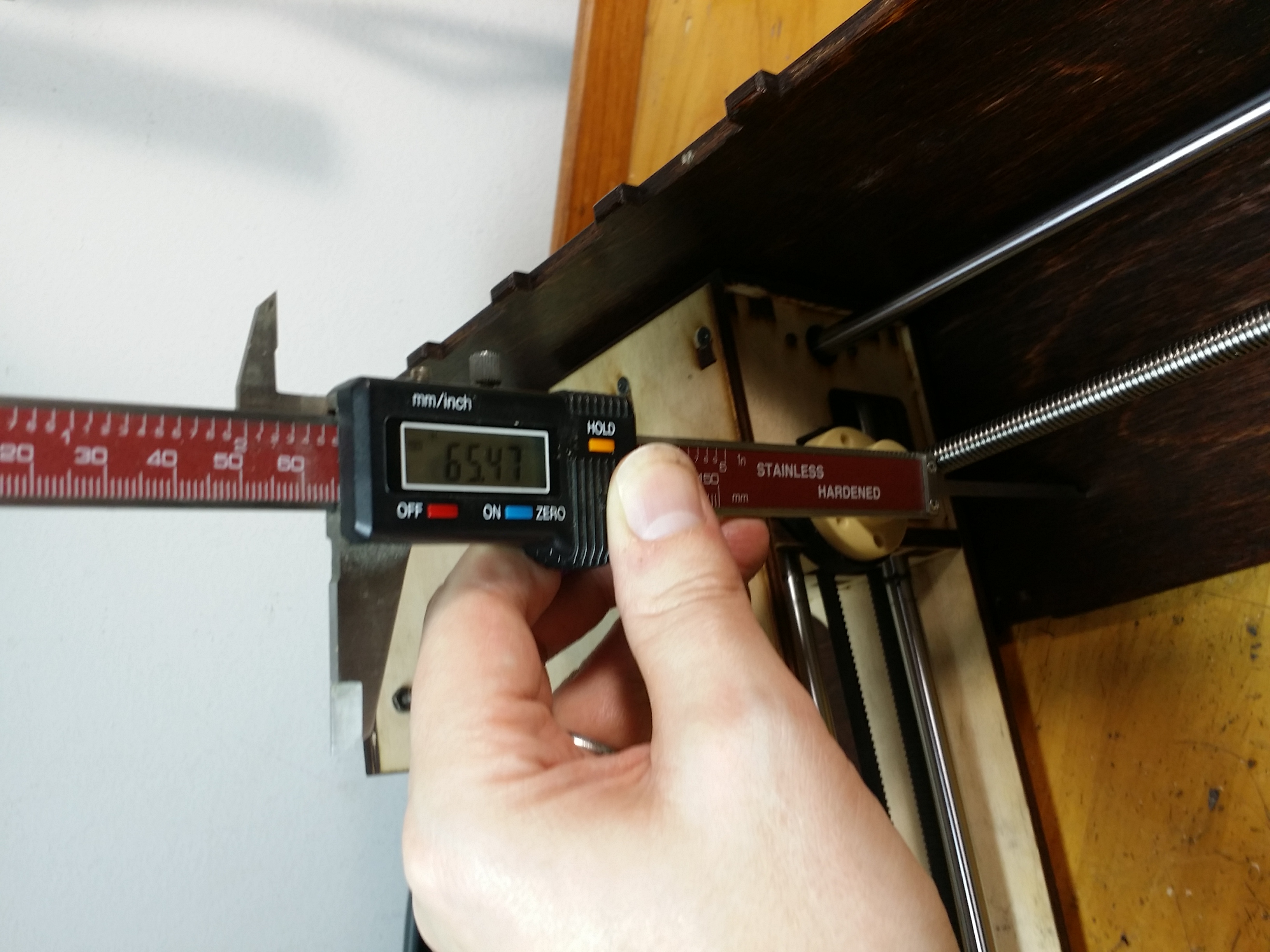
For now I’ve just trued up my threaded rods with my motor shafts as best I can and re-installed the CNC aluminum couplers I’d been using previously and I’ll just suck up the (thankfully at least predictable) Z wobble until I can address it properly. Grumble grumble grumble.
Do you happen to recall what material the Oldham couplers you bought were made of? It looks like Aluminum and some sort of plastic, but was it a low-friction, self-lubricating plastic like Delrin?
I’m considering making a custom set of couplers for my build and will use Aluminum and Igus’ proprietary iglide J material, which supposedly has a lower coefficient of friction than even Delrin!
The connectors are Al but I have no clue about the plastic bit in the middle. It feels like Delrin or something like that. I’ve only got about 100 printing hours or so on them, but they’re holding up well with no sign of wear. Iglide would probably be pretty sweet.