Oldham couplers, if you’re reading this, it wasn’t your fault. It was mine. I didn’t understand you. You were perfect. Will you ever forgive me?
So while deeply lost in thought about completely redesigning the gantry for the GO v.1 and agonizing over what kind of couplers really are best for my bot, a helpful chap on Google+ (+Joe Spanier) said, “Oldham couplers HAVE to have thrust bearings… to work correctly.”
Of course this makes sense. Oldham couplers are only designed to transmit rotation from one shaft to another while allowing for an offset of some potentially indeterminate amount. They are not designed to take load along their axis of rotation.
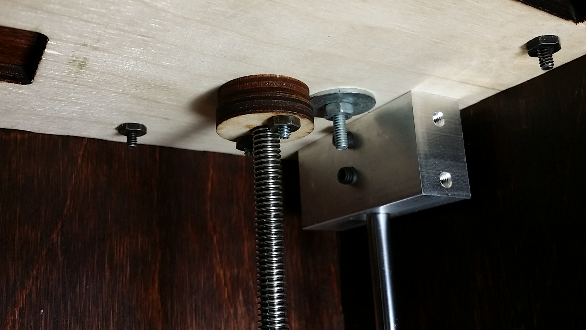
Well, at first I thought how in the heck could I support the load above the coupler in a way that wouldn’t completely destroy the advantage that the coupler is supposed to provide? Then it occurred to me that the load should be carried at the top of the bot and the lead screws should hang from thrust bearings with the Oldham couplers (all the way at the bottom) just providing rotation (as designed). I started cruising Amazon looking at thrust bearing designs and thinking about how to fit them into the top of the bot when it occurred to me that I could just make my own.
I’ve got some random bits of virgin PTFE rod stock that I make stuff out of from time to time (all watchmakers have some weird crap lying around) so after some head scratching and taking a few measurements I came up with a pretty simple design that I thought would work. I used the wooden donuts that came with the bot as the “housing” for the bearings and made some PTFE bushings that would fit neatly inside (and smoothly around the small diameter I had already turned on the top of the lead screws). Then I machined a recess into one side of the wooden donut just big enough for some smallish washers I had and machined a deeper recess in the other side to accommodate the same type of washer and also a pin for the lead screw to hang from. I drilled a hole in the end of each lead screw and reamed it out just enough so I could drive the pin in (a piece of blued steel) so that it wouldn’t fall out over time. And voila.
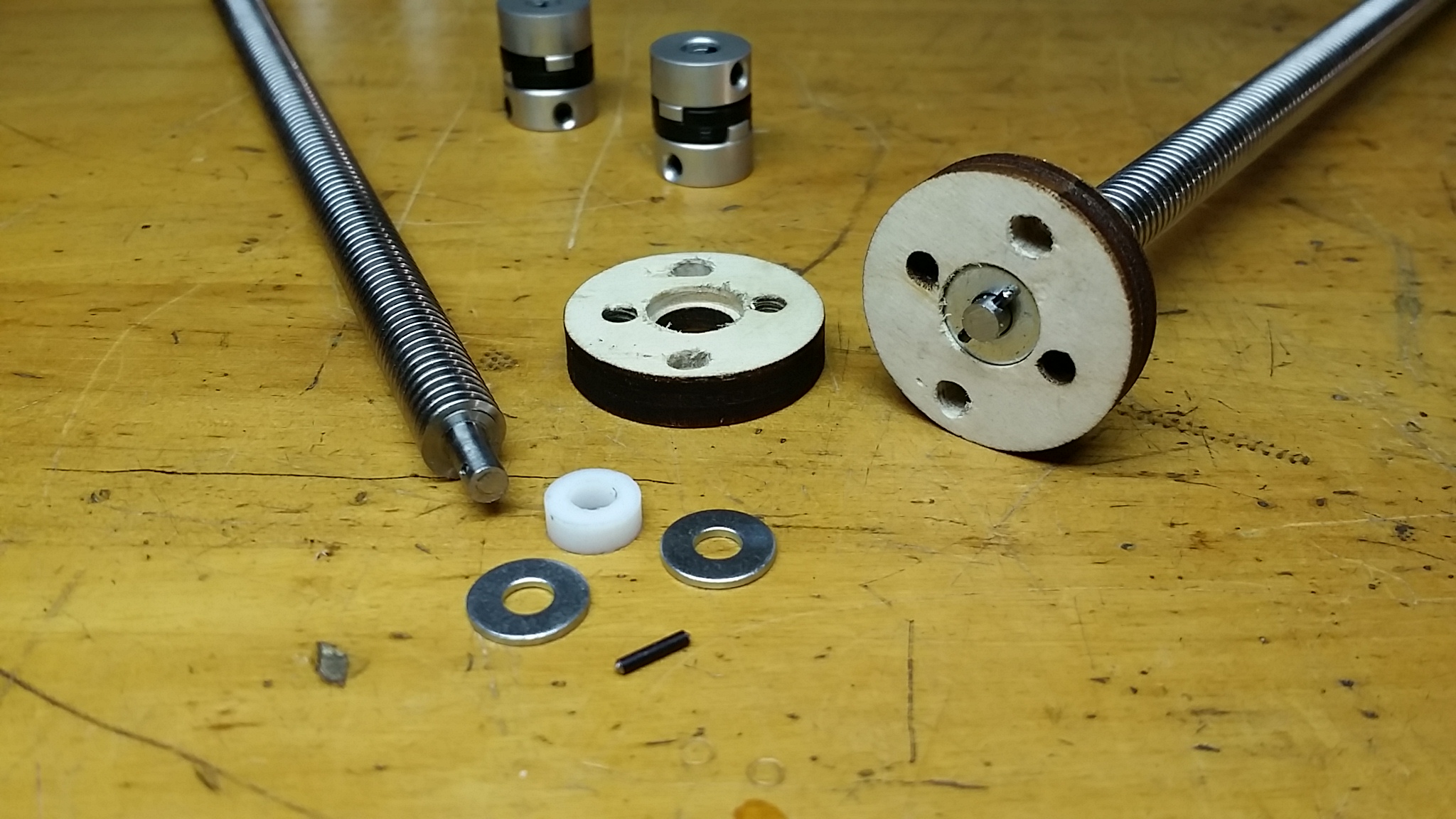
These particular wooden donuts have two sets of screw holes because they were originally intended for a different part of the bot and had to have a second set of holes drilled in them for this application. So then I just used the other wooden donuts to hold the whole thing together and stuck them in the top of the bot.
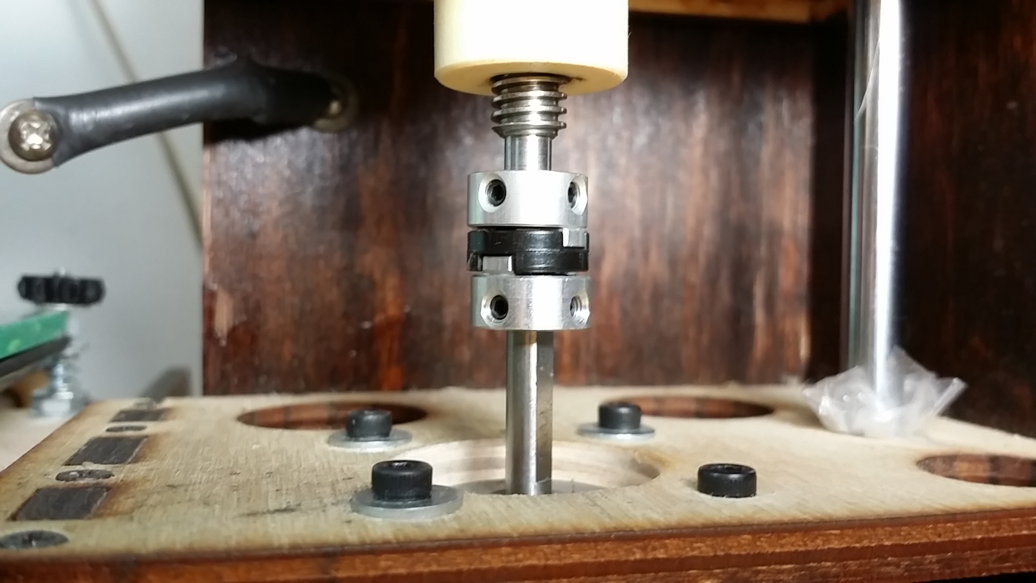
I had to futz with the proper height of the Oldham coupler halves on the motor shafts and lead screws and may even end up putting a couple of washers in as spacers above the thrust bearings to drop the lead screws down a smidge, but they’re working just great even with a little daylight showing through the connections in the couplers.
And the initial prints have been FANTASTICALLY improved. So good in fact that I can stop obsessing over Z artifacts and actually make some stuff. Or maybe start obsessing over slicer artifacts. Or start experimenting with my 1.75 mm hot end. Lots to do still.
Here’s a short video I took of them in action when printing a spiral vase sliced model.
And Brook, if you’re reading this, let me strongly urge you to experiment with thrust bearings and Oldham couplers in your new GO printers. The box design makes it fantastically more practical to incorporate hanging thrust bearings for the lead screws than most 3d printer designs out there, and they have made a HUGE improvement for me (so far, who knows how badly I’ll hate them by next week).
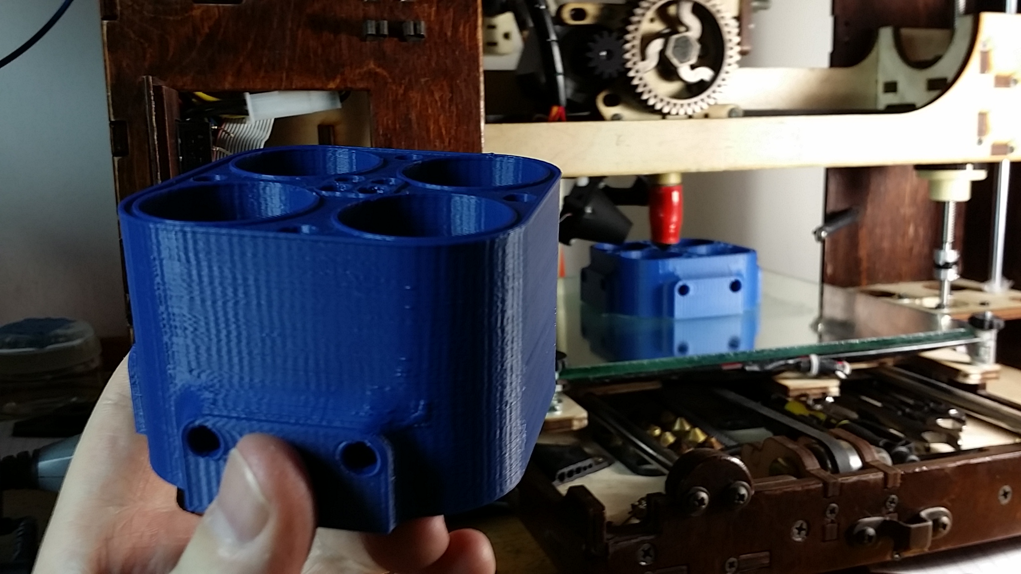
These parts are prototypes for Romar Basz, who is working on some ideas about converting water into hydrogen and oxygen.
I’m not seeing in that picture what slicing artifacts you’re talking about, but if you mean the slight waviness of what should be smooth sides, that looks more like you need to tune the current to your stepper motors than slicing artifacts.
Thanks for your comments!
Yeah, that picture didn’t show them well, but I’m referring to short, layer specific deformations in an outer wall that coincide with feature changes on an adjacent wall (for example). I’ve been experimenting with Cura vs Slic3r vs KISSlicer for different models and have found that each one has some models that it handles “better” in one way or another than others but I can’t find any pattern to it or a good way to predict which one will be best and of course it’s not practical to just print a copy with each one to see which I prefer for every part.
I’m sure I do need to properly tune my stepper drivers but have not yet found a way to do so that I’m 100% sold on. Using the method indicated in this blog post (http://erlblog.lewin.nu/2012/12/printrbot-plus-stepper-motor-current.html?m=1) seemed to give me voltages that were too high (making the motors pretty loud at least) and I really want to feel like I’m doing something repeatable rather than just adjusting the pots by “feel”. Any suggestions?
Im glad they worked for you! I’ve used Oldhams in mill and cnc router builds and loved them. I learned their benefits from an old maintenance machinist I used to work with that was always full of great info. Good luck with your slicer fun!