Sometimes we do things that are foolish. While it may indeed be a good idea to bevel some of the exterior edges on the GO, it was decidedly not a good idea to spend a lot of time and effort on this before actually assembling the thing. Birch ply wood is a great material for an assembly such as this because it is inexpensive and can be easily brought to shape on a laser cutter. It does not however hold up particularly well to detailing and the size of the wood screws and the perilously-close-to-the-edge placement of same means that some of the edges are going to crack, chip or otherwise take some damage during the assembly. Beveling and cleaning up after assembly? Good idea. Before? Not so much. More on this later.
For those of you unfamiliar with RepRaps and other consumer level 3d printers, there are a number of different approaches to getting movement in the X, Y and Z axis. Printrbot’s move the X axis up and down along Z while the print bed moves back and forth along the Y axis. For the GO, the Y axis is also the part that must slide out and then fold up to be secured in “suitcase mode”.
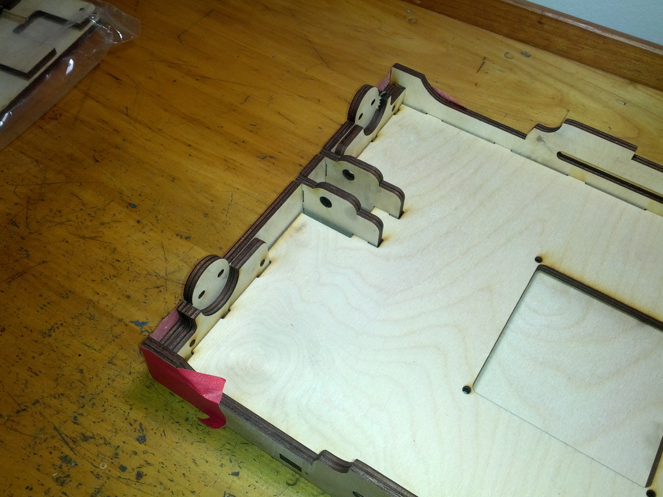
The Y assembly on my GO arrived assembled in so much as the main parts were in place and held together with red painters’ tape. I’m assuming this was just to make my life easier. If I hadn’t wanted to sand the wood I probably could have just started screwing it together without even taking off the tape.
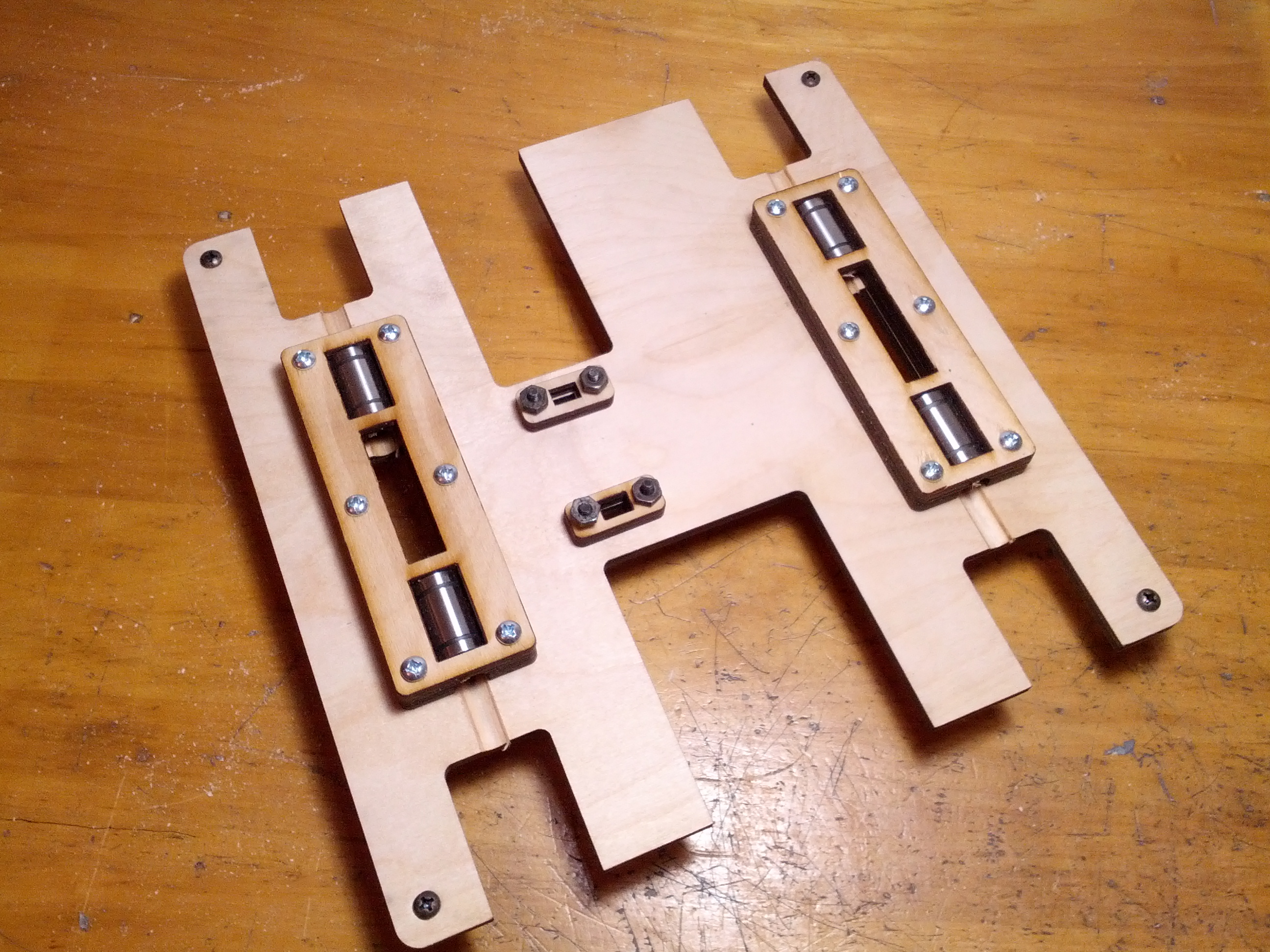
The linear bearing carriage assemblies for both the Y and X axis also came pre-assembled and this undoubtedly saved me some time and potential aggravation.
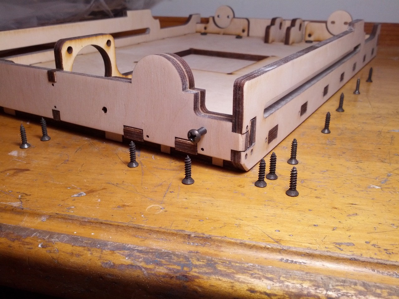
There are a LOT of wood screws in this design and basically all of them need to be countersunk. (Note: Brook said in the instructions that all of these wood screws are not really needed and that it would be up to me to decide how many to use. Who are we kidding though? I’m going to use all the screws. I may even add some more.) Especially on the left and right sides of the Y assembly, if the screw heads stick up they’ll keep the tray from sliding in and out of the bot smoothly.
To facilitate countersinking, I purchased some countersinking drill bits and this cute little hand powered drill.
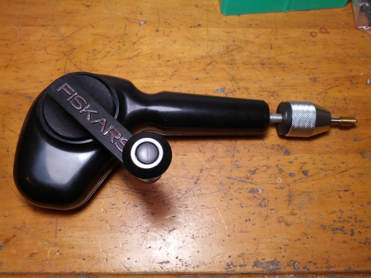
It was quite inexpensive and my thinking was that it would give me very precise control over the depth of my countersinks. It’s a little bit of a hassle to use in certain instances because it requires two hands (I end up holding pieces down with my elbow a lot), but it works well and is better than a power drill at two A.M. I honestly can’t say that it gives me any more control, but I like it just fine and am actually using it for all the drilling so far.
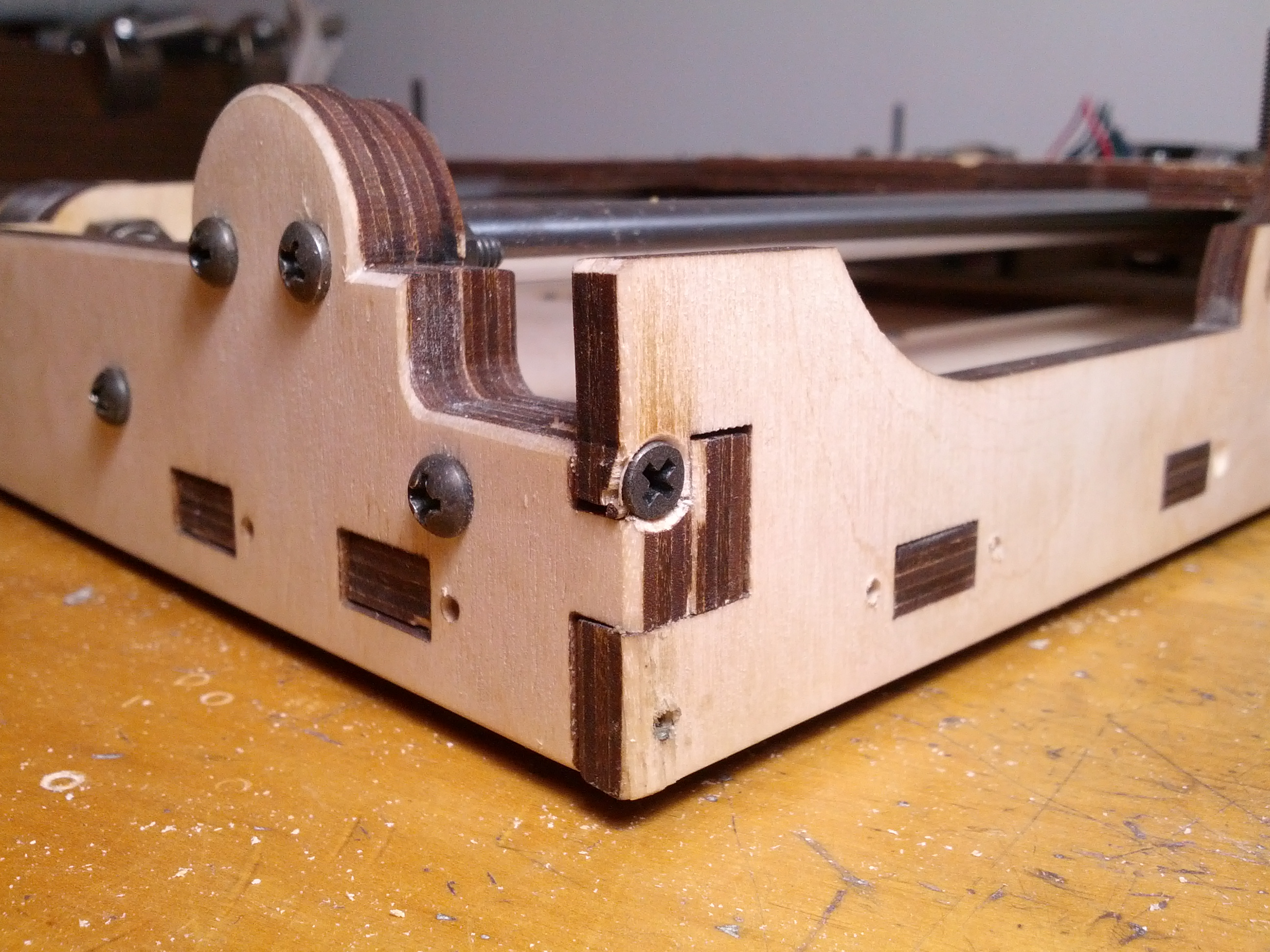
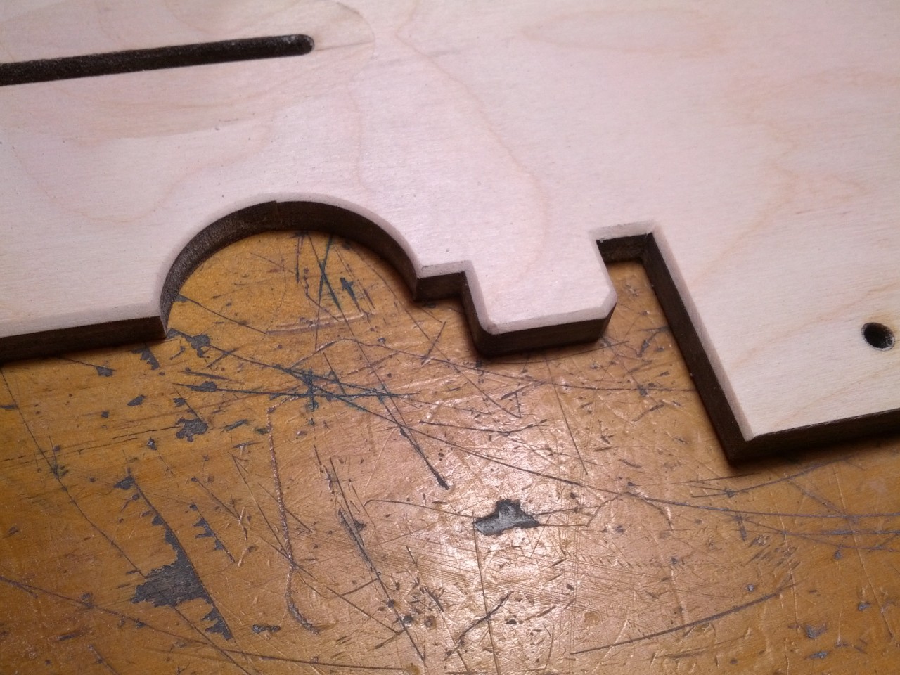
So here’s the problems with that detailing I did to the edges. First off, this is a questionable place for a screw of this size (I know, I’m deflecting, I’ll own up in a second). This is a tiny little tab on the side panel that is reaching around the tab of the interior piece and trying to just secure the screw into the side of the exterior (front) panel. This arrangement could stand a design tweak.
I looked at it and said to myself, “That’s a questionable place for a screw of that size,” but rather than countersinking and placing some of the other screws to see how the edges of the wood would hold up, I just decided to do this one first. Dumb. No other words for it. I could have easily found a smaller screw for that particular tab and saved myself the tears, but instead, I’ve botched the edge of one of the panels that will be front and center on the outside of the bot when it’s folded up into suitcase mode.
The worst part? This little bit of damage is right next to those painstaking bevels I put on previously AND I can’t say that the extent to which I beveled the edge of that tab didn’t weaken it and contribute to the failure. Surely there is a lesson about pride and immaturity here. I’m am not open to discussing that possibility however, thank you.
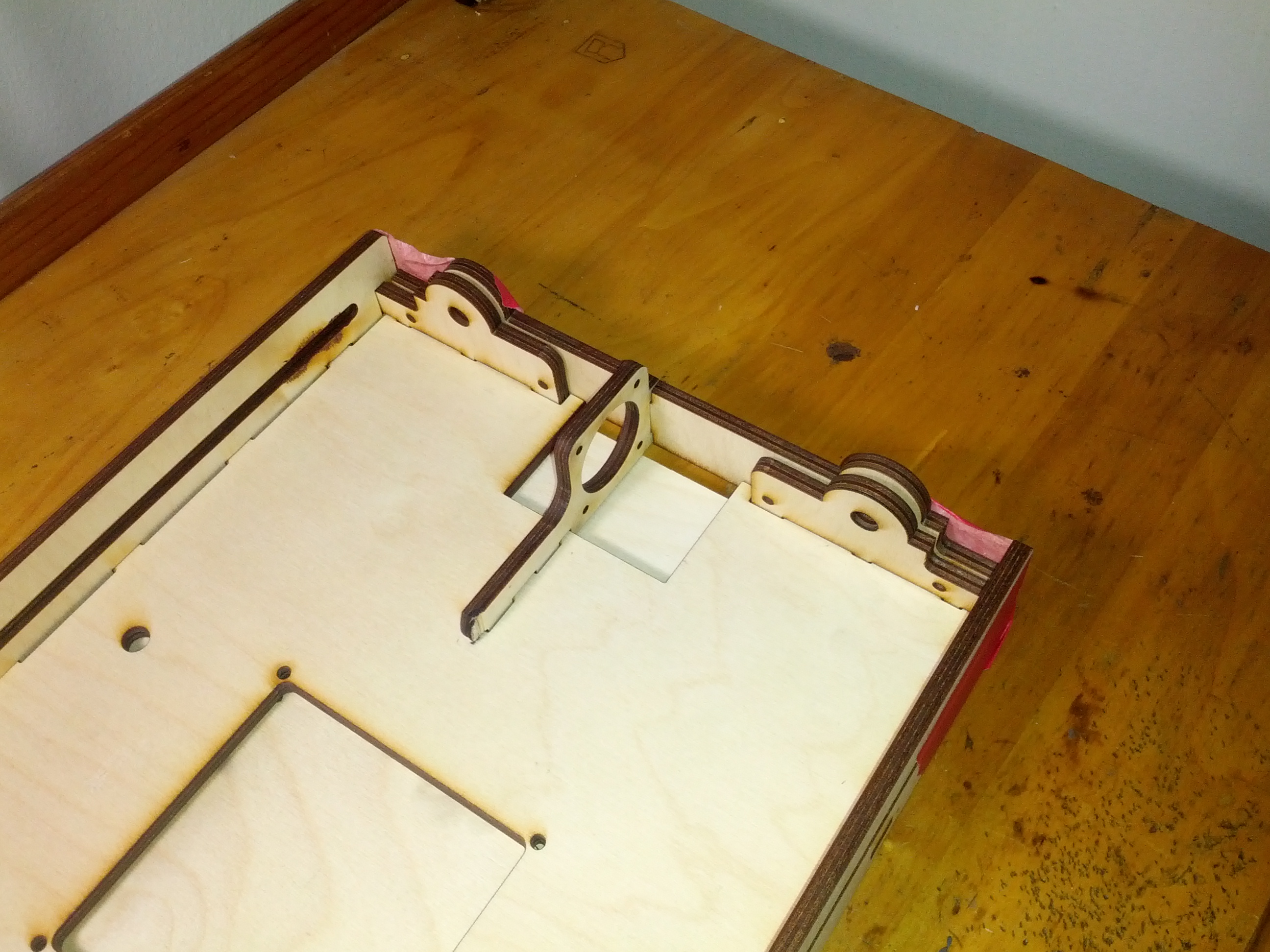
So here’s where I’m at now (plus a few more screws not pictured).
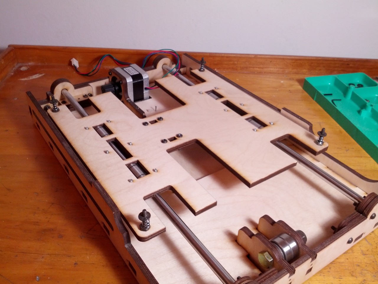
I’m not 100% sure how the adjustable print bed is supposed to go together, so I just did what made sense to me. I fed some screws up through the carriage and secured them with nuts, then put the springs and washers on top of those. The bed will sit on top of those and I’ve ordered some nylon thumb nuts to adjust the height with (I’ve actually ordered all kinds of alternate hardware, most of which I could only find in quantities of 100 pieces, I’m hoping Printrbot will let me send the leftovers their way once it’s all said and done). Printrbot uses wood thumb nuts for their bed leveling upgrade for the Printrbot +, and it makes sense to me that you want something relatively heat insulating here since you probably will want to level the bed when it’s already hot from time to time. Can the nylon stand up to the heat? We shall see.
I’ve ordered an 8″ x 8″ x 3/16″ thick mirror to use as the actual printing surface which will go on top of the heated print bed. Not sure what to do about insulation underneath the heated bed yet and I also need to think long and hard about how best to secure the mirror to the heated bed also. Since the whole Y assembly folds up for travel, the last thing I want is the mirror flopping out and getting me seven years bad luck. If that happens in front of the TSA it could be bad.
Some other things remaining with the Y assembly are the Y axis end stop (a little switch that tells the bot what “0” in the Y direction looks like) which I plan to mount with screws and nuts in a little track to make it adjustable (the standard attachment is with a zip tie) and figuring out how best to secure the wires from the motor, end stop and heated bed. I’m going to wait until the build is further along to figure that part out though. Brook mentioned in the instructions that he’s been unplugging these connections when folding it up AND that bad things can happen if you forget to plug them back in before turning on the bot, so I’m hoping I can figure out an arrangement that allows them to remain plugged in. Fingers crossed, but I’ll need to get a good look at how everything fits together before I can possibly hope to figure that out.